Information governor
BOSCH
9 420 612 849
9420612849
ZEXEL
105400-7550
1054007550
ISUZU
8970493270
8970493270

Rating:
Scheme ###:
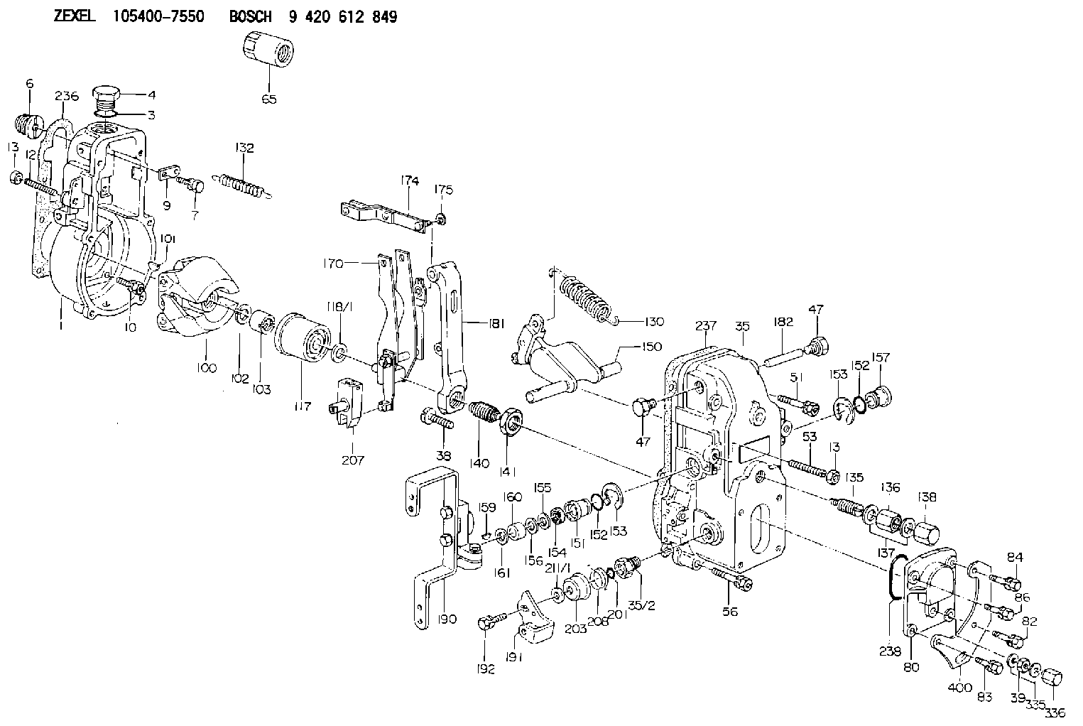
| 1. | [1] | 154000-6300 | GOVERNOR HOUSING |
| 3. | [1] | 029632-5070 | O-RING |
| 4. | [1] | 154007-2900 | CAPSULE |
| 6. | [1] | 154007-0200 | ADAPTOR |
| 7. | [1] | 020018-1840 | BLEEDER SCREW M8P1.25L18 |
| 9. | [1] | 154350-1900 | PLATE |
| 10. | [6] | 029010-6810 | BLEEDER SCREW |
| 12. | [1] | 154010-0100 | FLAT-HEAD SCREW |
| 13. | [2] | 154011-0100 | HEXAGON NUT |
| 13. | [2] | 154011-0100 | HEXAGON NUT |
| 35. | [1] | 154500-1020 | GOVERNOR COVER |
| 35/2. | [1] | 154321-0400 | BUSHING |
| 38. | [1] | 154031-2400 | FLAT-HEAD SCREW |
| 39. | [1] | 139206-0600 | UNION NUT |
| 47. | [2] | 154036-0300 | CAPSULE |
| 47. | [2] | 154036-0300 | CAPSULE |
| 51. | [2] | 020106-5040 | BLEEDER SCREW |
| 53. | [1] | 154010-0200 | FLAT-HEAD SCREW |
| 56. | [4] | 020106-3840 | BLEEDER SCREW |
| 65. | [1] | 155404-5700 | CAP |
| 80. | [1] | 154063-1400 | COVER |
| 82. | [1] | 029020-6260 | BLEEDER SCREW |
| 83. | [1] | 029020-6260 | BLEEDER SCREW |
| 84. | [1] | 020006-2040 | BLEEDER SCREW M6P1L20 4T |
| 86. | [1] | 020006-1640 | BLEEDER SCREW M6P1L16 4T |
| 100. | [1] | 154101-0020 | FLYWEIGHT ASSEMBLY |
| 101. | [1] | 025803-1610 | WOODRUFF KEY |
| 102. | [1] | 029321-2020 | LOCKING WASHER |
| 103. | [1] | 029231-2030 | UNION NUT |
| 117. | [1] | 154123-2320 | SLIDING PIECE |
| 118/1. | [0] | 029311-0010 | SHIM D14&10.1T0.2 |
| 118/1. | [0] | 029311-0180 | SHIM D14&10.1T0.3 |
| 118/1. | [0] | 029311-0190 | SHIM D14&10.1T0.40 |
| 118/1. | [0] | 029311-0210 | SHIM D14&10.1T1 |
| 118/1. | [0] | 139410-0000 | SHIM D14.0&10.1T0.5 |
| 118/1. | [0] | 139410-0100 | SHIM D14.0&10.1T1.5 |
| 118/1. | [0] | 139410-3000 | SHIM D14&10.1T2.0 |
| 118/1. | [0] | 139410-3100 | SHIM D14&10.1T3.0 |
| 118/1. | [0] | 139410-3200 | SHIM D14&10.1T4.0 |
| 130. | [1] | 154150-0100 | GOVERNOR SPRING |
| 132. | [1] | 154154-0800 | COILED SPRING |
| 135. | [1] | 154158-0820 | HEADLESS SCREW |
| 136. | [1] | 154011-1700 | UNION NUT |
| 137. | [2] | 026512-1540 | GASKET D15.4&12.2T1.50 |
| 138. | [1] | 154159-1200 | CAP NUT |
| 140. | [1] | 154178-9220 | HEADLESS SCREW |
| 141. | [1] | 029201-6010 | UNION NUT |
| 150. | [1] | 154200-7020 | SWIVELLING LEVER |
| 151. | [1] | 154204-3000 | BUSHING |
| 152. | [2] | 029631-8020 | O-RING |
| 152. | [2] | 029631-8020 | O-RING |
| 153. | [2] | 016010-1640 | LOCKING WASHER |
| 153. | [2] | 016010-1640 | LOCKING WASHER |
| 154. | [1] | 139611-0000 | PACKING RING |
| 155. | [1] | 139411-0000 | SHIM |
| 156. | [0] | 029311-1070 | SHIM D16&11T0.5 |
| 157. | [1] | 154204-3100 | BUSHING |
| 159. | [1] | 025803-1310 | WOODRUFF KEY |
| 160. | [1] | 154206-2800 | BUSHING |
| 161. | [0] | 154206-0200 | PLAIN WASHER D19.5&11.2T1.0 |
| 170. | [1] | 154210-7320 | FORK LEVER |
| 174. | [1] | 154230-3920 | STRAP |
| 175. | [1] | 016010-0540 | LOCKING WASHER |
| 181. | [1] | 154236-4100 | TENSIONING LEVER |
| 182. | [1] | 154237-0100 | BEARING PIN |
| 190. | [1] | 154343-4920 | CONTROL LEVER |
| 191. | [1] | 154367-1900 | CONTROL LEVER |
| 192. | [1] | 020006-1640 | BLEEDER SCREW M6P1L16 4T |
| 201. | [1] | 029631-0030 | O-RING &9.8W2.3 |
| 203. | [1] | 154322-0100 | CAP |
| 207. | [1] | 154326-5020 | CONTROL LEVER |
| 208. | [1] | 154327-7600 | COILED SPRING |
| 211/1. | [0] | 029311-0520 | SHIM D20.8&10.3T0.2 |
| 211/1. | [0] | 029311-0530 | SHIM D20.8&10.3T0.25 |
| 211/1. | [0] | 029311-0540 | SHIM D20.8&10.3T0.3 |
| 211/1. | [0] | 029311-0550 | SHIM D20.8&10.3T0.35 |
| 211/1. | [0] | 029311-0560 | SHIM D20.8&10.3T0.4 |
| 211/1. | [0] | 029311-0570 | SHIM D20.8&10.3T0.5 |
| 236. | [1] | 154390-0000 | GASKET |
| 237. | [1] | 154390-0300 | GASKET |
| 238. | [1] | 029635-2020 | O-RING |
| 335. | [2] | 026506-1040 | GASKET D9.9&6.2T1 |
| 336. | [1] | 154035-1600 | CAP NUT |
| 400. | [1] | 154358-7200 | BRACKET |
Include in #1:
101492-0640
as GOVERNOR
Cross reference number
Zexel num
Bosch num
Firm num
Name
105400-7550
8970493270 ISUZU
GOVERNOR
K 14JB MECHANICAL GOVERNOR GOV RSV GOV
K 14JB MECHANICAL GOVERNOR GOV RSV GOV
Information:
Self-Diagnostics
The 3176 Truck Engine has a limited ability to diagnose itself. When the System detects a problem, a Diagnostic Code is generated which activates the Diagnostic Lamp. In most cases the code will be stored in permanent memory in the ECM.Diagnostic Codes that represent current faults are called ACTIVE and indicate that a problem exists. These active diagnostic codes should be investigated first.Diagnostic Codes stores in memory are called LOGGED. The problem may have been temporary or repaired since the time it was LOGGED. These codes may not mean something needs to be repaired, but may be helpful indicators when INTERMITTENT problems exist, which could be used to troubleshoot and analyze potential problems. In addition, some logged diagnostic codes record events and performance history, rather than failures.Diagnostic Codes-Interpretation
When the vehicle is equipped with Cruise Control (CC)
1. Turn ignition key ON (engine does not need to be started to view codes).2. The Diagnostic Lamp will illuminate for five seconds, blink off, turn on again for five seconds, then off for five seconds. The lamp will then begin to flash the first number of the two-digit code (count the flashes). The lamp will blink off for two seconds, then begin to flash the second number of the two-digit code in the same manner as the first. If more than one code is present, they will follow the first code after a few seconds and be displayed in the same manner.3. Active diagnostic codes may be displayed at any time by using the Cruise Control (CC) Switches. The engine can be running or the ignition key ON. Turn the Cruise Control ON/OFF switch to OFF and move the SET/RESUME switch to RESUME position. The Check Engine Light will flash to indicate a 2-digit fault code and the switch may be released from the RESUME position.When the vehicle is NOT equipped with Cruise Control (CC):
Some trucks are equipped with a Check Engine Light Switch to check diagnostic codes. The Check Engine Light can be used to communicate the specific 3176 system diagnostic fault. The Check Engine light will flash to indicate the 2-digit diagnostic fault code. This can be done by connecting a push button momentary switch from position H of connector P7 thru the momentary switch and back to position B of connector P7.With the switch depressed, the "Check Engine" light will begin to flash. The sequence of flashes represents the 3176 system diagnostic message.The first sequence of flashes adds up to the first digit of the diagnostic code. After a two second pause, a second sequence of flashes will occur which represents the second digit of the diagnostic code. Any additional codes will follow and will be displayed in the same manner.Refer to 3176 Truck Engine Test Procedures, Form SENR5112 and the Service Manual for troubleshooting the 3176 System. For further information or assistance for repairs, contact an authorized Caterpillar dealer.Some trucks have electronic dashboards that provide a direct readout of 3176 engine diagnostic codes. Follow the truck manufacturer's instructions