Information governor
BOSCH
9 420 612 848
9420612848
ZEXEL
105400-7340
1054007340
ISUZU
8970452890
8970452890
Rating:
Scheme ###:
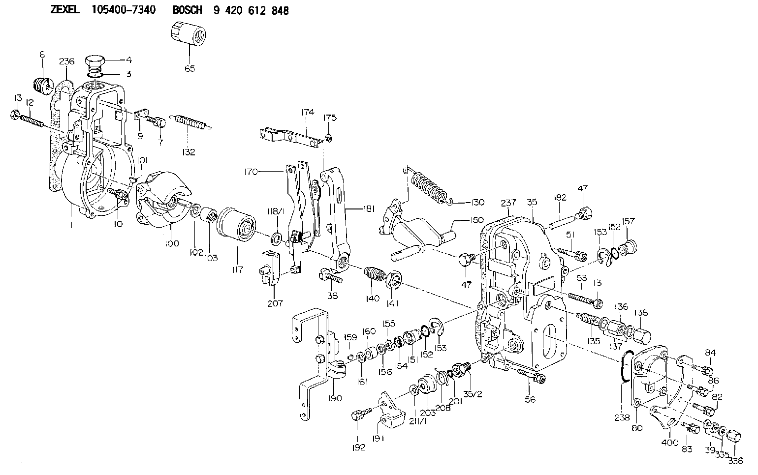
| 1. | [1] | 154000-6300 | GOVERNOR HOUSING |
| 3. | [1] | 029632-5070 | O-RING |
| 4. | [1] | 154007-2900 | CAPSULE |
| 6. | [1] | 154007-0200 | ADAPTOR |
| 7. | [1] | 020018-1840 | BLEEDER SCREW M8P1.25L18 |
| 9. | [1] | 154350-1900 | PLATE |
| 10. | [6] | 029010-6810 | BLEEDER SCREW |
| 12. | [1] | 154010-1100 | FLAT-HEAD SCREW |
| 13. | [2] | 154011-0100 | HEXAGON NUT |
| 13. | [2] | 154011-0100 | HEXAGON NUT |
| 35. | [1] | 154500-1020 | GOVERNOR COVER |
| 35/2. | [1] | 154321-0400 | BUSHING |
| 38. | [1] | 154031-2400 | FLAT-HEAD SCREW |
| 39. | [1] | 139206-0600 | UNION NUT |
| 47. | [2] | 154036-0300 | CAPSULE |
| 47. | [2] | 154036-0300 | CAPSULE |
| 51. | [2] | 020106-5040 | BLEEDER SCREW |
| 53. | [1] | 154010-0200 | FLAT-HEAD SCREW |
| 56. | [4] | 020106-3840 | BLEEDER SCREW |
| 65. | [1] | 155404-5700 | CAP |
| 80. | [1] | 154063-1400 | COVER |
| 82. | [1] | 029020-6260 | BLEEDER SCREW |
| 83. | [1] | 029020-6260 | BLEEDER SCREW |
| 84. | [1] | 020006-2040 | BLEEDER SCREW M6P1L20 4T |
| 86. | [1] | 020006-1640 | BLEEDER SCREW M6P1L16 4T |
| 100. | [1] | 154101-0120 | FLYWEIGHT |
| 101. | [1] | 025803-1610 | WOODRUFF KEY |
| 102. | [1] | 029321-2020 | LOCKING WASHER |
| 103. | [1] | 029231-2030 | UNION NUT |
| 117. | [1] | 154123-2320 | SLIDING PIECE |
| 118/1. | [0] | 029311-0010 | SHIM D14&10.1T0.2 |
| 118/1. | [0] | 029311-0180 | SHIM D14&10.1T0.3 |
| 118/1. | [0] | 029311-0190 | SHIM D14&10.1T0.40 |
| 118/1. | [0] | 029311-0210 | SHIM D14&10.1T1 |
| 118/1. | [0] | 139410-0000 | SHIM D14.0&10.1T0.5 |
| 118/1. | [0] | 139410-0100 | SHIM D14.0&10.1T1.5 |
| 118/1. | [0] | 139410-3000 | SHIM D14&10.1T2.0 |
| 118/1. | [0] | 139410-3100 | SHIM D14&10.1T3.0 |
| 118/1. | [0] | 139410-3200 | SHIM D14&10.1T4.0 |
| 130. | [1] | 154150-6400 | GOVERNOR SPRING |
| 132. | [1] | 154154-0800 | COILED SPRING |
| 135. | [1] | 154158-0820 | HEADLESS SCREW |
| 136. | [1] | 154011-1700 | UNION NUT |
| 137. | [2] | 026512-1540 | GASKET D15.4&12.2T1.50 |
| 138. | [1] | 154159-1200 | CAP NUT |
| 140. | [1] | 154185-4020 | HEADLESS SCREW |
| 141. | [1] | 029201-6010 | UNION NUT |
| 150. | [1] | 154200-7020 | SWIVELLING LEVER |
| 151. | [1] | 154204-3000 | BUSHING |
| 152. | [2] | 029631-8020 | O-RING |
| 152. | [2] | 029631-8020 | O-RING |
| 153. | [2] | 016010-1640 | LOCKING WASHER |
| 153. | [2] | 016010-1640 | LOCKING WASHER |
| 154. | [1] | 139611-0000 | PACKING RING |
| 155. | [1] | 139411-0000 | SHIM |
| 156. | [0] | 029311-1070 | SHIM D16&11T0.5 |
| 157. | [1] | 154204-3100 | BUSHING |
| 159. | [1] | 025803-1310 | WOODRUFF KEY |
| 160. | [1] | 154206-2800 | BUSHING |
| 161. | [0] | 154206-0200 | PLAIN WASHER D19.5&11.2T1.0 |
| 170. | [1] | 154210-0920 | FORK LEVER |
| 174. | [1] | 154230-3920 | STRAP |
| 175. | [1] | 016010-0540 | LOCKING WASHER |
| 181. | [1] | 154236-4100 | TENSIONING LEVER |
| 182. | [1] | 154237-0100 | BEARING PIN |
| 190. | [1] | 154343-4920 | CONTROL LEVER |
| 191. | [1] | 154367-1900 | CONTROL LEVER |
| 192. | [1] | 020006-1640 | BLEEDER SCREW M6P1L16 4T |
| 201. | [1] | 029631-0030 | O-RING &9.8W2.3 |
| 203. | [1] | 154322-0100 | CAP |
| 207. | [1] | 154326-5020 | CONTROL LEVER |
| 208. | [1] | 154327-7600 | COILED SPRING |
| 211/1. | [0] | 029311-0520 | SHIM D20.8&10.3T0.2 |
| 211/1. | [0] | 029311-0530 | SHIM D20.8&10.3T0.25 |
| 211/1. | [0] | 029311-0540 | SHIM D20.8&10.3T0.3 |
| 211/1. | [0] | 029311-0550 | SHIM D20.8&10.3T0.35 |
| 211/1. | [0] | 029311-0560 | SHIM D20.8&10.3T0.4 |
| 211/1. | [0] | 029311-0570 | SHIM D20.8&10.3T0.5 |
| 236. | [1] | 154390-0000 | GASKET |
| 237. | [1] | 154390-0300 | GASKET |
| 238. | [1] | 029635-2020 | O-RING |
| 335. | [2] | 026506-1040 | GASKET D9.9&6.2T1 |
| 336. | [1] | 154035-1600 | CAP NUT |
| 400. | [1] | 154358-7200 | BRACKET |
Include in #1:
101482-4470
as GOVERNOR
Cross reference number
Zexel num
Bosch num
Firm num
Name
105400-7340
8970452890 ISUZU
GOVERNOR
K 14JB MECHANICAL GOVERNOR GOV RSV GOV
K 14JB MECHANICAL GOVERNOR GOV RSV GOV
Information:
Caterpillar's Scheduled Oil Sampling (S O S) Program is a series of diagnostic tests designed to identify and measure contamination and condition of oil in an engine's crankcase. S O S is also used to determine oil performance and component wear rates and is the best indicator for determining what is happening inside your engine.Caterpillar recommends using Scheduled Oil Sampling (S O S), at regularly scheduled intervals, to compliment a good preventive maintenance program.The Caterpillar Scheduled Oil Sampling Program (S O S), was developed to help Caterpillar users realize the highest possible value from their equipment by minimizing repair costs and maximizing availability. The S O S program is a series of diagnostic tests which analyze used lubricating oils from the oil wetted compartments of the equipment. By analyzing the used oils, problems may be identified early, before extensive component failure occurs. This reduces repair cost and down-time.The S O S program is coupled with a wide range of repair options so that when a problem is identified, an appropriate matched repair plan is available. This offers the user a more complete service to minimize repair costs and schedule down-time. S O S can also measure the effectiveness of the user's maintenance program.S O S Analysis
S O S is composed of three basic tests:* Wear Analysis* Chemical and Physical Tests* Oil Condition Analysis Wear Analysis is performed with an atomic absorption spectrophotometer to monitor component wear rates by identifying and measuring concentrations, in parts per million, of wear elements present in the used oil.Based on known normal concentration data, maximum limits of wear elements are established. Impending failures can be identified when test results deviate from concentration levels established as acceptable, based on normal wear.Through monitoring the used oil, normal component wear trends are determined. Many failures can be identified when wear trends and/or contaminants significantly exceed past trends.Detectable failures are those caused by component wear and gradual contamination from dirt, fuel, water or antifreeze. Wear analysis is not able to predict failures due to component fatigue, sudden loss of lubrication, or sudden ingestion of a large amount of dirt or contaminants since failures of this nature occur too rapidly. Chemical and Physical Tests detect the presence of water, fuel and/or glycol (antifreeze) in the oil and determine whether or not their concentrations exceed established maximum limits. Oil Condition Analysis is evaluated with Infrared Analysis and determines the degree of deterioration of the used oil by measuring the amount of contaminants such as sulfur products, oxidation, nitration products and soot present in the used oil.It also monitors additive depletion and detects ethylene glycol and butyl cellosolve contamination and can assist in customizing (reducing, maintaining or extending) oil change intervals for particular conditions and applications.Oil Condition Analysis can help regulate (reduce, maintain or extend), oil change intervals for a specific engine in a given application and MUST always be used with Wear Element Analysis and Chemical and Physical Tests to assure accurate diagnosis. Infrared Analysis must be used to
S O S is composed of three basic tests:* Wear Analysis* Chemical and Physical Tests* Oil Condition Analysis Wear Analysis is performed with an atomic absorption spectrophotometer to monitor component wear rates by identifying and measuring concentrations, in parts per million, of wear elements present in the used oil.Based on known normal concentration data, maximum limits of wear elements are established. Impending failures can be identified when test results deviate from concentration levels established as acceptable, based on normal wear.Through monitoring the used oil, normal component wear trends are determined. Many failures can be identified when wear trends and/or contaminants significantly exceed past trends.Detectable failures are those caused by component wear and gradual contamination from dirt, fuel, water or antifreeze. Wear analysis is not able to predict failures due to component fatigue, sudden loss of lubrication, or sudden ingestion of a large amount of dirt or contaminants since failures of this nature occur too rapidly. Chemical and Physical Tests detect the presence of water, fuel and/or glycol (antifreeze) in the oil and determine whether or not their concentrations exceed established maximum limits. Oil Condition Analysis is evaluated with Infrared Analysis and determines the degree of deterioration of the used oil by measuring the amount of contaminants such as sulfur products, oxidation, nitration products and soot present in the used oil.It also monitors additive depletion and detects ethylene glycol and butyl cellosolve contamination and can assist in customizing (reducing, maintaining or extending) oil change intervals for particular conditions and applications.Oil Condition Analysis can help regulate (reduce, maintain or extend), oil change intervals for a specific engine in a given application and MUST always be used with Wear Element Analysis and Chemical and Physical Tests to assure accurate diagnosis. Infrared Analysis must be used to