Information governor
BOSCH
9 420 610 293
9420610293
ZEXEL
105400-6510
1054006510
Rating:
Scheme ###:
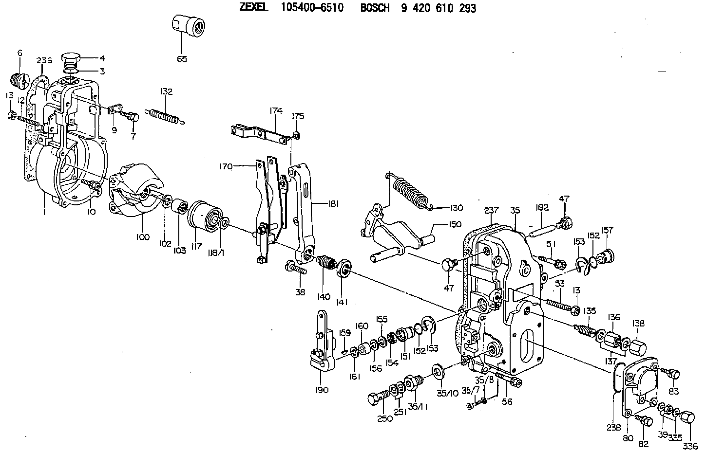
| 1. | [1] | 154000-6300 | GOVERNOR HOUSING |
| 3. | [1] | 029632-5070 | O-RING |
| 4. | [1] | 154007-2900 | CAPSULE |
| 6. | [1] | 154007-0200 | ADAPTOR |
| 7. | [1] | 020018-1840 | BLEEDER SCREW M8P1.25L18 |
| 9. | [1] | 154350-1900 | PLATE |
| 10. | [6] | 029010-6810 | BLEEDER SCREW |
| 12. | [1] | 154010-0100 | FLAT-HEAD SCREW |
| 13. | [2] | 154011-0100 | HEXAGON NUT |
| 13. | [2] | 154011-0100 | HEXAGON NUT |
| 35. | [1] | 154500-8720 | GOVERNOR COVER |
| 35/7. | [1] | 154222-2700 | FLAT-HEAD SCREW |
| 35/8. | [1] | 014110-3440 | LOCKING WASHER |
| 35/10. | [1] | 026516-2040 | GASKET D19.9&16.2T1 |
| 35/11. | [1] | 154316-6600 | ADAPTOR |
| 38. | [1] | 154031-2400 | FLAT-HEAD SCREW |
| 39. | [1] | 139206-0600 | UNION NUT |
| 47. | [2] | 154036-0300 | CAPSULE |
| 47. | [2] | 154036-0300 | CAPSULE |
| 51. | [2] | 020106-5040 | BLEEDER SCREW |
| 53. | [1] | 154010-0300 | FLAT-HEAD SCREW |
| 56. | [4] | 020106-3840 | BLEEDER SCREW |
| 65. | [1] | 154050-1720 | STOPPING DEVICE |
| 80. | [1] | 154063-1400 | COVER |
| 82. | [2] | 029020-6210 | BLEEDER SCREW |
| 83. | [2] | 020006-1640 | BLEEDER SCREW M6P1L16 4T |
| 100. | [1] | 154101-0120 | FLYWEIGHT |
| 102. | [1] | 029321-2020 | LOCKING WASHER |
| 103. | [1] | 029231-2030 | UNION NUT |
| 117. | [1] | 154123-0120 | SLIDING PIECE |
| 118/1. | [0] | 029311-0010 | SHIM D14&10.1T0.2 |
| 118/1. | [0] | 029311-0180 | SHIM D14&10.1T0.3 |
| 118/1. | [0] | 029311-0190 | SHIM D14&10.1T0.40 |
| 118/1. | [0] | 029311-0210 | SHIM D14&10.1T1 |
| 118/1. | [0] | 139410-0000 | SHIM D14.0&10.1T0.5 |
| 118/1. | [0] | 139410-0100 | SHIM D14.0&10.1T1.5 |
| 118/1. | [0] | 139410-3000 | SHIM D14&10.1T2.0 |
| 118/1. | [0] | 139410-3100 | SHIM D14&10.1T3.0 |
| 118/1. | [0] | 139410-3200 | SHIM D14&10.1T4.0 |
| 130. | [1] | 154150-2700 | GOVERNOR SPRING |
| 132. | [1] | 154154-0701 | COILED SPRING |
| 135. | [1] | 154158-0820 | HEADLESS SCREW |
| 136. | [1] | 154011-1700 | UNION NUT |
| 137. | [2] | 026512-1540 | GASKET D15.4&12.2T1.50 |
| 138. | [1] | 154159-1200 | CAP NUT |
| 140. | [1] | 154177-0320 | HEADLESS SCREW |
| 141. | [1] | 029201-6010 | UNION NUT |
| 150. | [1] | 154200-7120 | SWIVELLING LEVER |
| 151. | [1] | 154204-3000 | BUSHING |
| 152. | [2] | 029631-8020 | O-RING |
| 152. | [2] | 029631-8020 | O-RING |
| 153. | [2] | 016010-1640 | LOCKING WASHER |
| 153. | [2] | 016010-1640 | LOCKING WASHER |
| 154. | [1] | 139611-0000 | PACKING RING |
| 155. | [1] | 139411-0000 | SHIM |
| 156. | [0] | 029311-1070 | SHIM D16&11T0.5 |
| 157. | [1] | 154204-3100 | BUSHING |
| 159. | [1] | 025803-1310 | WOODRUFF KEY |
| 160. | [1] | 154206-2800 | BUSHING |
| 161. | [0] | 154206-0200 | PLAIN WASHER D19.5&11.2T1.0 |
| 170. | [1] | 154210-0920 | FORK LEVER |
| 174. | [1] | 154230-3920 | STRAP |
| 175. | [1] | 016010-0540 | LOCKING WASHER |
| 181. | [1] | 154236-1500 | TENSIONING LEVER |
| 182. | [1] | 154237-0100 | BEARING PIN |
| 190. | [1] | 154341-9520 | CONTROL LEVER |
| 236. | [1] | 154390-0000 | GASKET |
| 237. | [1] | 154390-0300 | GASKET |
| 238. | [1] | 029635-2020 | O-RING |
| 250. | [1] | 029731-2040 | EYE BOLT |
| 251. | [2] | 029341-2140 | GASKET |
| 335. | [2] | 026506-1040 | GASKET D9.9&6.2T1 |
| 336. | [1] | 154035-1600 | CAP NUT |
Include in #1:
101695-3320
as GOVERNOR
Cross reference number
Zexel num
Bosch num
Firm num
Name
Information:
Marks For Tightening Connecting Rod Bolts-7E5996 Connecting Rod Assembly(1) Bore in connecting rod for piston pin bearing ... 55.436 0.013 mm (2.1825 .0005 in) The connecting rod must be heated for installation of piston pin bearing. Do not use a torch.(2) Distance rod may be heated to 175 to 260°C (347 to 500°F) to install the piston pin bearing ... 85.0 mm (3.35 in)(3) Bore in bearing for piston pin (new) ... 50.830 0.008 mm (2.0012 .0003 in) Diameter of piston pin (new) ... 50.795 0.005 mm (1.9998 .0002 in)Thoroughly lubricate piston pin with clean engine oil prior to inserting into piston group and rod assembly.Maximum permissible clearance between bearing and piston pin (worn) ... 0.25 mm (.010 in)(4) Bearing joint must be assembled at either location on centerline through the connecting rod bore ... 5°Make reference to Special Instruction, Form No. SMHS7295 for use of pin bearing removal and installation tools and procedures.(5) Distance between center of bearings ... 261.62 0.05 mm (10.300 .002 in)(6) Bore in connecting rod for bearing with nuts tightened to specifications (8) ... 96.200 0.013 mm (3.7874 .0005 in)(7) Location for etching cylinder number on connecting rod and cap. Rods and caps are to be marked with numbers 1 through 6 on the same side of the rod as the bearing tab slots.(8) Tighten connecting rod bolts as follows: a. Before installing bolts, lubricate bolt threads and seating faces of the caps with 2P2506 Thread Lubricant.b. Tighten each bolt to ... 90 8 N m (66 6 lb ft)c. Put an alignment mark on each cap and bolt.d. Tighten each bolt an additional ... 90 5° (1/4 turn)(9) Bore in bearing for crankshaft rod journal ... 90.112 0.028 mm (3.5477 .0011 in) Clearance between bearing and crankshaft (new) ... 0.062 to 0.160 mm (.0024 to .0063 in)Maximum permissible clearance between bearing and crankshaft (worn) ... 0.20 mm (.008 in) Bearings are available in 0.63 mm (.025 in) and 1.27 mm (.050 in) smaller than original size.