Information governor
BOSCH
9 420 612 073
9420612073
ZEXEL
105400-6280
1054006280
HINO
223203080A
223203080a
Rating:
Scheme ###:
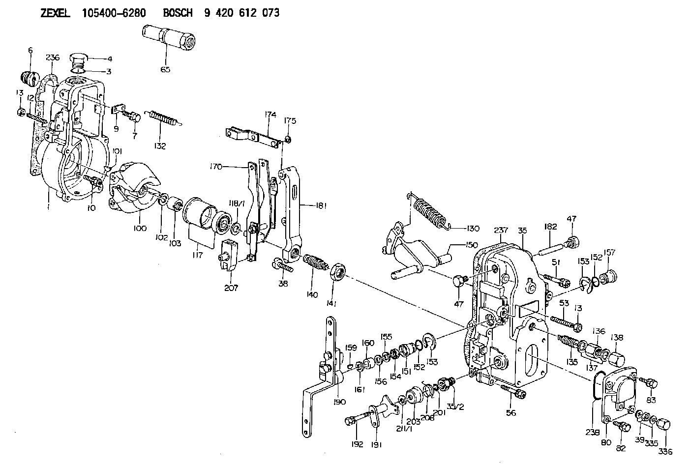
| 1. | [1] | 154000-9700 | GOVERNOR HOUSING |
| 3. | [1] | 029632-5070 | O-RING |
| 4. | [1] | 154007-2900 | CAPSULE |
| 6. | [1] | 154007-0200 | ADAPTOR |
| 7. | [1] | 020018-1840 | BLEEDER SCREW M8P1.25L18 |
| 9. | [1] | 154350-1900 | PLATE |
| 10. | [6] | 029010-6810 | BLEEDER SCREW |
| 12. | [1] | 154010-1100 | FLAT-HEAD SCREW |
| 13. | [2] | 154011-0100 | HEXAGON NUT |
| 13. | [2] | 154011-0100 | HEXAGON NUT |
| 35. | [1] | 154500-1020 | GOVERNOR COVER |
| 35/2. | [1] | 154321-0400 | BUSHING |
| 38. | [1] | 154031-2400 | FLAT-HEAD SCREW |
| 39. | [1] | 139206-0600 | UNION NUT |
| 47. | [2] | 154036-0300 | CAPSULE |
| 47. | [2] | 154036-0300 | CAPSULE |
| 51. | [2] | 020106-5040 | BLEEDER SCREW |
| 53. | [1] | 154010-0100 | FLAT-HEAD SCREW |
| 56. | [4] | 020106-3840 | BLEEDER SCREW |
| 65. | [1] | 153020-3720 | STOPPING DEVICE |
| 80. | [1] | 154063-1400 | COVER |
| 82. | [2] | 029020-6210 | BLEEDER SCREW |
| 83. | [2] | 020006-1640 | BLEEDER SCREW M6P1L16 4T |
| 100. | [1] | 154101-0120 | FLYWEIGHT |
| 101. | [1] | 025803-1610 | WOODRUFF KEY |
| 102. | [1] | 029321-2020 | LOCKING WASHER |
| 103. | [1] | 029231-2030 | UNION NUT |
| 117. | [1] | 154123-0120 | SLIDING PIECE |
| 118/1. | [0] | 029311-0010 | SHIM D14&10.1T0.2 |
| 118/1. | [0] | 029311-0180 | SHIM D14&10.1T0.3 |
| 118/1. | [0] | 029311-0190 | SHIM D14&10.1T0.40 |
| 118/1. | [0] | 029311-0210 | SHIM D14&10.1T1 |
| 118/1. | [0] | 139410-0000 | SHIM D14.0&10.1T0.5 |
| 118/1. | [0] | 139410-0100 | SHIM D14.0&10.1T1.5 |
| 118/1. | [0] | 139410-3000 | SHIM D14&10.1T2.0 |
| 118/1. | [0] | 139410-3100 | SHIM D14&10.1T3.0 |
| 118/1. | [0] | 139410-3200 | SHIM D14&10.1T4.0 |
| 130. | [1] | 154150-2900 | GOVERNOR SPRING |
| 132. | [1] | 154154-0800 | COILED SPRING |
| 135. | [1] | 154158-1520 | HEADLESS SCREW |
| 136. | [1] | 154011-1700 | UNION NUT |
| 137. | [2] | 026512-1540 | GASKET D15.4&12.2T1.50 |
| 138. | [1] | 154159-1200 | CAP NUT |
| 140. | [1] | 154185-3920 | HEADLESS SCREW |
| 141. | [1] | 029201-6010 | UNION NUT |
| 150. | [1] | 154200-7020 | SWIVELLING LEVER |
| 151. | [1] | 154204-3000 | BUSHING |
| 152. | [2] | 029631-8020 | O-RING |
| 152. | [2] | 029631-8020 | O-RING |
| 153. | [2] | 016010-1640 | LOCKING WASHER |
| 153. | [2] | 016010-1640 | LOCKING WASHER |
| 154. | [1] | 139611-0000 | PACKING RING |
| 155. | [1] | 139411-0000 | SHIM |
| 156. | [0] | 029311-1070 | SHIM D16&11T0.5 |
| 157. | [1] | 154204-3100 | BUSHING |
| 159. | [1] | 025803-1310 | WOODRUFF KEY |
| 160. | [1] | 154206-2800 | BUSHING |
| 161. | [0] | 154206-0200 | PLAIN WASHER D19.5&11.2T1.0 |
| 170. | [1] | 154210-0920 | FORK LEVER |
| 174. | [1] | 154230-3920 | STRAP |
| 175. | [1] | 016010-0540 | LOCKING WASHER |
| 181. | [1] | 154236-4100 | TENSIONING LEVER |
| 182. | [1] | 154237-0100 | BEARING PIN |
| 190. | [1] | 154341-8120 | CONTROL LEVER |
| 191. | [1] | 154367-7220 | CONTROL LEVER |
| 192. | [1] | 020006-2540 | BLEEDER SCREW M6P1L25 |
| 201. | [1] | 029631-0030 | O-RING &9.8W2.3 |
| 203. | [1] | 154322-0100 | CAP |
| 207. | [1] | 154326-5020 | CONTROL LEVER |
| 208. | [1] | 154327-3400 | COILED SPRING |
| 211/1. | [0] | 029311-0520 | SHIM D20.8&10.3T0.2 |
| 211/1. | [0] | 029311-0530 | SHIM D20.8&10.3T0.25 |
| 211/1. | [0] | 029311-0540 | SHIM D20.8&10.3T0.3 |
| 211/1. | [0] | 029311-0550 | SHIM D20.8&10.3T0.35 |
| 211/1. | [0] | 029311-0560 | SHIM D20.8&10.3T0.4 |
| 211/1. | [0] | 029311-0570 | SHIM D20.8&10.3T0.5 |
| 236. | [1] | 154390-1300 | GASKET |
| 237. | [1] | 154390-0300 | GASKET |
| 238. | [1] | 029635-2020 | O-RING |
| 335. | [2] | 026506-1040 | GASKET D9.9&6.2T1 |
| 336. | [1] | 154035-1600 | CAP NUT |
Include in #1:
101602-2510
as GOVERNOR
Cross reference number
Zexel num
Bosch num
Firm num
Name
105400-6280
223203080A HINO
GOVERNOR
K 14JB MECHANICAL GOVERNOR GOV RSV GOV
K 14JB MECHANICAL GOVERNOR GOV RSV GOV
Information:
Keep all parts clean from contaminants. Contaminants put into the system may cause rapid wear and shortened component life.
1. Loosen hose clamps and slide hose (1) down on the tube assembly. 2. Remove tube assembly (4).3. Disconnect hose assembly (3), loosen two clamps and slide hose (2) on tube assembly. 4. Remove bolts (5). 5. Remove the supply tube (6) and drain tube (7) and the gaskets. 6. Disconnect tube assembly (8) from the aftercooler housing and remove bolts (9).7. Attach a hoist to the cylinder head lift brackets. 8. Remove head bolts (10) and the cylinder head from the engine block. The weight of the cylinder head assembly is 177 kg (390 lb).
Do not set the cylinder head on a flat surface because of possible damage to the fuel injection nozzle tips.
Install Cylinder Head
When the cylinder head is removed, a new spacer plate gasket must be installed. See the topic, Remove And Install Spacer Plate, in this manual. 1. Clean the surfaces of the cylinder head and the cylinder block that make contact with each other. Make sure the surfaces are clean and dry. Install a new dry gasket (2) on the cylinder block.2. Fasten a hoist to the cylinder head (1) and put it on position on the cylinder block.3. Put 6V4876 Molykote Lubricant on all the head bolts and rocker shaft bolts except bolt (25). Install the head bolts and washers that hold the head in place. Do not tighten bolts at this time.4. Loosen the adjusting screws on the rocker arms for valve clearance. This will prevent a bent valve or push rod at installation. 5. Install push rods (4) and rocker shaft assembly (3). Install the bolts and washers that hold the rocker shaft in place. 6. Tighten the bolts as follows:a. Tighten bolts 1 through 26 in number sequence to a torque of 155 N m (115 lb ft).b. Tighten bolts 1 through 26 again in number sequence to a torque of 250 17 N m (185 13 lb ft).c. Tighten bolts 1 through 26 again in number sequence (hand tighten only) to a torque of 250 17 N m (185 13 lb ft).d. Tighten bolts A through G in letter sequence (hand tighten only) to a torque of 43 7 N m (32 5 lb ft). 6. Make an adjustment until the intake valve clearance is 0.38 mm (.015 in) and the exhaust valve clearance is 0.64 mm (.025 in). Tighten the locknuts (5) for the adjusting screws to a torque of 29 7 N m (21 5 lb ft).7. Connect tube assembly (6) and install the bolts to fasten clips (7). 8. Inspect the turbocharger cartridge gaskets and make replacements if necessary. Install gaskets and the turbocharger supply tube assembly (8) and drain tube assembly (9). 9. Make sure the gasket for the water pump bypass elbow is in good condition and install two bolts (11) to fasten elbow (12) to cylinder