Information governor
BOSCH
9 420 613 452
9420613452
ZEXEL
105400-5960
1054005960
HINO
223202760A
223202760a

Rating:
Scheme ###:
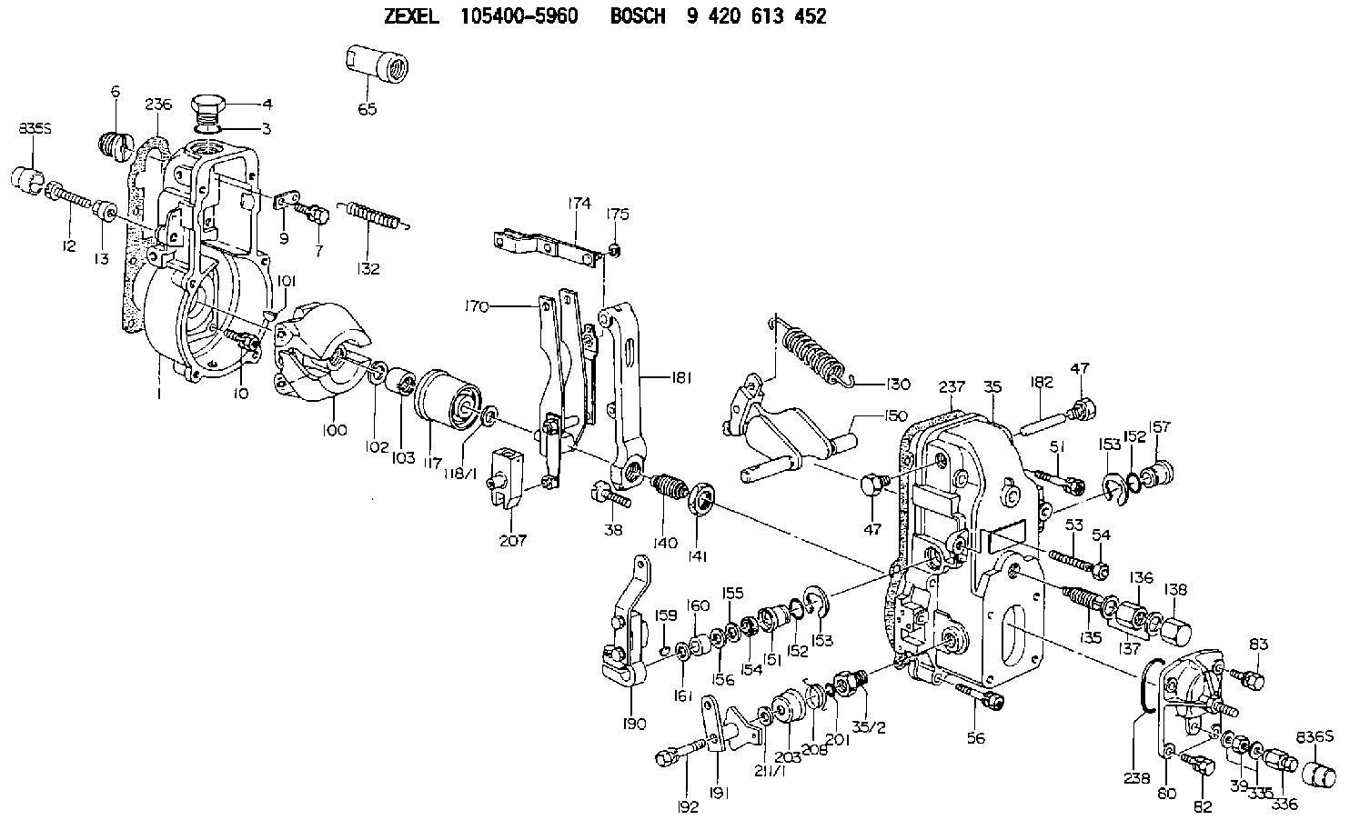
| 1. | [1] | 154000-6300 | GOVERNOR HOUSING |
| 3. | [1] | 029632-5070 | O-RING |
| 4. | [1] | 154007-2900 | CAPSULE |
| 6. | [1] | 154007-0200 | ADAPTOR |
| 7. | [1] | 020018-1840 | BLEEDER SCREW M8P1.25L18 |
| 9. | [1] | 154350-1900 | PLATE |
| 10. | [6] | 029010-6810 | BLEEDER SCREW |
| 12. | [1] | 154013-0600 | BLEEDER SCREW |
| 12B. | [1] | 154010-7300 | BLEEDER SCREW M8P1.25L60 |
| 13. | [1] | 154011-0100 | HEXAGON NUT |
| 35. | [1] | 154500-1020 | GOVERNOR COVER |
| 35/2. | [1] | 154321-0400 | BUSHING |
| 38. | [1] | 154031-2400 | FLAT-HEAD SCREW |
| 39. | [1] | 139206-0600 | UNION NUT |
| 47. | [2] | 154036-0300 | CAPSULE |
| 47. | [2] | 154036-0300 | CAPSULE |
| 51. | [2] | 020106-5040 | BLEEDER SCREW |
| 53. | [1] | 154010-0100 | FLAT-HEAD SCREW |
| 54. | [1] | 154011-2300 | UNION NUT |
| 56. | [4] | 020106-3840 | BLEEDER SCREW |
| 65. | [1] | 154050-6120 | STOPPING DEVICE |
| 80. | [1] | 154063-7420 | COVER |
| 82. | [2] | 029020-6210 | BLEEDER SCREW |
| 83. | [2] | 020006-1640 | BLEEDER SCREW M6P1L16 4T |
| 100. | [1] | 154101-0520 | FLYWEIGHT |
| 101. | [1] | 025803-1610 | WOODRUFF KEY |
| 102. | [1] | 029321-2020 | LOCKING WASHER |
| 103. | [1] | 029231-2030 | UNION NUT |
| 117. | [1] | 154123-0120 | SLIDING PIECE |
| 118/1. | [0] | 029311-0010 | SHIM D14&10.1T0.2 |
| 118/1. | [0] | 029311-0180 | SHIM D14&10.1T0.3 |
| 118/1. | [0] | 029311-0190 | SHIM D14&10.1T0.40 |
| 118/1. | [0] | 029311-0210 | SHIM D14&10.1T1 |
| 118/1. | [0] | 139410-0000 | SHIM D14.0&10.1T0.5 |
| 118/1. | [0] | 139410-0100 | SHIM D14.0&10.1T1.5 |
| 118/1. | [0] | 139410-3000 | SHIM D14&10.1T2.0 |
| 118/1. | [0] | 139410-3100 | SHIM D14&10.1T3.0 |
| 118/1. | [0] | 139410-3200 | SHIM D14&10.1T4.0 |
| 130. | [1] | 154150-2700 | GOVERNOR SPRING |
| 132. | [1] | 154154-0800 | COILED SPRING |
| 135. | [1] | 154158-0820 | HEADLESS SCREW |
| 136. | [1] | 154011-1700 | UNION NUT |
| 137. | [2] | 026512-1540 | GASKET D15.4&12.2T1.50 |
| 138. | [1] | 154159-1200 | CAP NUT |
| 140. | [1] | 154177-0720 | HEADLESS SCREW |
| 141. | [1] | 029201-6010 | UNION NUT |
| 150. | [1] | 154200-7120 | SWIVELLING LEVER |
| 151. | [1] | 154204-3000 | BUSHING |
| 152. | [2] | 029631-8020 | O-RING |
| 152. | [2] | 029631-8020 | O-RING |
| 153. | [2] | 016010-1640 | LOCKING WASHER |
| 153. | [2] | 016010-1640 | LOCKING WASHER |
| 154. | [1] | 139611-0000 | PACKING RING |
| 155. | [1] | 139411-0000 | SHIM |
| 156. | [0] | 029311-1070 | SHIM D16&11T0.5 |
| 157. | [1] | 154204-3100 | BUSHING |
| 159. | [1] | 025803-1310 | WOODRUFF KEY |
| 160. | [1] | 154206-2800 | BUSHING |
| 161. | [0] | 154206-0200 | PLAIN WASHER D19.5&11.2T1.0 |
| 170. | [1] | 154210-7320 | FORK LEVER |
| 174. | [1] | 154230-3920 | STRAP |
| 175. | [1] | 016010-0540 | LOCKING WASHER |
| 181. | [1] | 154236-1500 | TENSIONING LEVER |
| 182. | [1] | 154237-0100 | BEARING PIN |
| 190. | [1] | 154303-3120 | CONTROL LEVER |
| 191. | [1] | 154307-5920 | CONTROL LEVER |
| 192. | [1] | 020006-3540 | BLEEDER SCREW |
| 201. | [1] | 029631-0030 | O-RING &9.8W2.3 |
| 203. | [1] | 154322-0100 | CAP |
| 207. | [1] | 154326-5020 | CONTROL LEVER |
| 208. | [1] | 154327-7600 | COILED SPRING |
| 211/1. | [0] | 029311-0520 | SHIM D20.8&10.3T0.2 |
| 211/1. | [0] | 029311-0530 | SHIM D20.8&10.3T0.25 |
| 211/1. | [0] | 029311-0540 | SHIM D20.8&10.3T0.3 |
| 211/1. | [0] | 029311-0550 | SHIM D20.8&10.3T0.35 |
| 211/1. | [0] | 029311-0560 | SHIM D20.8&10.3T0.4 |
| 211/1. | [0] | 029311-0570 | SHIM D20.8&10.3T0.5 |
| 236. | [1] | 154390-0000 | GASKET |
| 237. | [1] | 154390-0300 | GASKET |
| 238. | [1] | 029635-2020 | O-RING |
| 335. | [2] | 026506-1040 | GASKET D9.9&6.2T1 |
| 336. | [1] | 154035-2500 | CAP NUT |
Cross reference number
Zexel num
Bosch num
Firm num
Name
105400-5960
223202760A HINO
GOVERNOR
K 14JB MECHANICAL GOVERNOR GOV RSV GOV
K 14JB MECHANICAL GOVERNOR GOV RSV GOV
Information:
Start By:a. remove cylinder headb. remove oil panc. remove oil pumpd. remove cooling tubes 1. Check the connecting rods and caps for their identification and location.2. Remove rod cap nuts (1) and cap (2) from connecting rod (3). Remove the lower half of bearing (4) from cap (2).
To protect the crankshaft from the threaded portion of connecting rod bolts (5), cut a short piece of rubber hose and install it over both rod bolts (5).
3. Remove the piston and connecting rod, then remove the upper half of rod bearing (4). The following steps are for the installation of the pistons and connecting rod assemblies.4. Put clean oil on piston rings, connecting rod bearings and cylinder bore.5. Position the piston ring end gaps 120° apart and install tooling (A).6. Put the short pieces of hose over the threaded portion of rod bolts (5), to protect crankshaft.7. With number one crankshaft throw at bottom center, install the piston and connecting rod. Engines which use one piece pistons have the word "FRONT" stamped on the crown of the piston. Make sure the word "FRONT" is toward the front of the engine when the piston is installed.8. Taking care to line up connecting rod and crankshaft, carefully tap piston into cylinder bore until tooling (A) comes off the piston. 9. Before connecting rod (3) comes in contact with the crankshaft, install upper half of rod bearing (4). Be sure the bearing tab engages the groove in the connecting rod.10. Put engine oil on upper rod bearing surface, then tap piston down, guiding connecting rod onto crankshaft.11. Position lower half of rod bearing (4) in corresponding numbered rod cap (2). Be sure the bearing tab engages the grove in the rod caps.12. Put engine oil on the lower rod bearing surface, then install the rod cap. Install the bearing cap on the connecting rod with the number on the bearing (rod) cap on the same side and same number as on the connecting rod.13. Put engine oil on the threads of bolts (5). Install rod cap nuts (1) and tighten them to a torque of 54 7 N m (40 5 lb.ft.).14. Put an alignment mark on cap and nut. Then, tighten each nut an additional 60° 5° (1/6 turn).15. Repeat the steps for the remainder of the pistons and connecting rods.End By:a. install cooling tubesb. install oil pumpc. install oil pand. install cylinder headDisassemble And Assemble Pistons And Connecting Rods
Start By:a. remove pistons and connecting rods 1. Remove snap ring (1) remove piston pin (2). Separate piston (3) and connecting rod (4).
One Piece Piston
Two Piece Piston2. Use tooling (A) and remove piston rings (5). The following steps are for the assembly of the pistons and connecting rods.3. Check the clearance between the ends of the piston rings (5). See the topic, Pistons And Rings in the Specifications section of the service manual. The oil ring is to be installed over the spring with the end gap 180° from the