Information governor
BOSCH
9 420 612 069
9420612069
ZEXEL
105400-5911
1054005911
HINO
223202711A
223202711a

Rating:
Scheme ###:
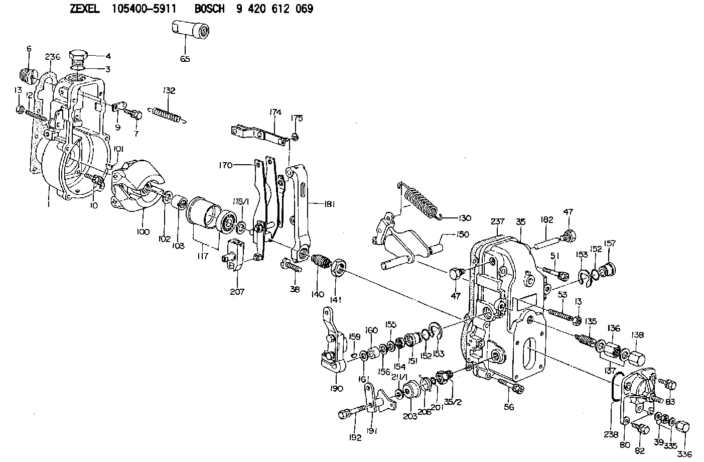
| 1. | [1] | 154000-6300 | GOVERNOR HOUSING |
| 3. | [1] | 029632-5070 | O-RING |
| 4. | [1] | 154007-2900 | CAPSULE |
| 6. | [1] | 154007-0200 | ADAPTOR |
| 7. | [1] | 020018-1840 | BLEEDER SCREW M8P1.25L18 |
| 9. | [1] | 154350-1900 | PLATE |
| 10. | [6] | 029010-6810 | BLEEDER SCREW |
| 12. | [1] | 154010-1100 | FLAT-HEAD SCREW |
| 13. | [2] | 154011-0100 | HEXAGON NUT |
| 13. | [2] | 154011-0100 | HEXAGON NUT |
| 35. | [1] | 154500-1020 | GOVERNOR COVER |
| 35/2. | [1] | 154321-0400 | BUSHING |
| 38. | [1] | 154031-2400 | FLAT-HEAD SCREW |
| 39. | [1] | 139206-0600 | UNION NUT |
| 47. | [2] | 154036-0300 | CAPSULE |
| 47. | [2] | 154036-0300 | CAPSULE |
| 51. | [2] | 020106-5040 | BLEEDER SCREW |
| 53. | [1] | 154010-0200 | FLAT-HEAD SCREW |
| 56. | [4] | 020106-3840 | BLEEDER SCREW |
| 65. | [1] | 154050-6120 | STOPPING DEVICE |
| 80. | [1] | 154063-7420 | COVER |
| 82. | [2] | 029020-6210 | BLEEDER SCREW |
| 83. | [2] | 020006-1640 | BLEEDER SCREW M6P1L16 4T |
| 100. | [1] | 154101-0320 | FLYWEIGHT ASSEMBLY |
| 101. | [1] | 025803-1610 | WOODRUFF KEY |
| 102. | [1] | 029321-2020 | LOCKING WASHER |
| 103. | [1] | 029231-2030 | UNION NUT |
| 117. | [1] | 154123-0120 | SLIDING PIECE |
| 118/1. | [0] | 029311-0010 | SHIM D14&10.1T0.2 |
| 118/1. | [0] | 029311-0180 | SHIM D14&10.1T0.3 |
| 118/1. | [0] | 029311-0190 | SHIM D14&10.1T0.40 |
| 118/1. | [0] | 029311-0210 | SHIM D14&10.1T1 |
| 118/1. | [0] | 139410-0000 | SHIM D14.0&10.1T0.5 |
| 118/1. | [0] | 139410-0100 | SHIM D14.0&10.1T1.5 |
| 118/1. | [0] | 139410-3000 | SHIM D14&10.1T2.0 |
| 118/1. | [0] | 139410-3100 | SHIM D14&10.1T3.0 |
| 118/1. | [0] | 139410-3200 | SHIM D14&10.1T4.0 |
| 130. | [1] | 154150-0400 | GOVERNOR SPRING |
| 132. | [1] | 154154-0800 | COILED SPRING |
| 135. | [1] | 154158-1320 | HEADLESS SCREW |
| 136. | [1] | 154011-2700 | UNION NUT |
| 137. | [2] | 026512-1540 | GASKET D15.4&12.2T1.50 |
| 138. | [1] | 154159-1200 | CAP NUT |
| 140. | [1] | 154185-2120 | HEADLESS SCREW |
| 141. | [1] | 029201-6010 | UNION NUT |
| 150. | [1] | 154200-7020 | SWIVELLING LEVER |
| 151. | [1] | 154204-4300 | BUSHING |
| 152. | [2] | 029631-8020 | O-RING |
| 152. | [2] | 029631-8020 | O-RING |
| 153. | [2] | 016010-1640 | LOCKING WASHER |
| 153. | [2] | 016010-1640 | LOCKING WASHER |
| 154. | [1] | 139611-0000 | PACKING RING |
| 155. | [1] | 139411-0000 | SHIM |
| 156. | [0] | 029311-1070 | SHIM D16&11T0.5 |
| 157. | [1] | 154204-4400 | BUSHING |
| 159. | [1] | 025803-1310 | WOODRUFF KEY |
| 160. | [1] | 154206-2800 | BUSHING |
| 161. | [0] | 154206-0200 | PLAIN WASHER D19.5&11.2T1.0 |
| 170. | [1] | 154210-7320 | FORK LEVER |
| 174. | [1] | 154230-3920 | STRAP |
| 175. | [1] | 016010-0540 | LOCKING WASHER |
| 181. | [1] | 154236-4100 | TENSIONING LEVER |
| 182. | [1] | 154237-0100 | BEARING PIN |
| 190. | [1] | 154345-8820 | CONTROL LEVER |
| 191. | [1] | 154367-6620 | CONTROL LEVER |
| 192. | [1] | 020006-3540 | BLEEDER SCREW |
| 201. | [1] | 029631-0030 | O-RING &9.8W2.3 |
| 203. | [1] | 154322-0100 | CAP |
| 207. | [1] | 154326-5020 | CONTROL LEVER |
| 208. | [1] | 154327-7600 | COILED SPRING |
| 211/1. | [0] | 029311-0520 | SHIM D20.8&10.3T0.2 |
| 211/1. | [0] | 029311-0530 | SHIM D20.8&10.3T0.25 |
| 211/1. | [0] | 029311-0540 | SHIM D20.8&10.3T0.3 |
| 211/1. | [0] | 029311-0550 | SHIM D20.8&10.3T0.35 |
| 211/1. | [0] | 029311-0560 | SHIM D20.8&10.3T0.4 |
| 211/1. | [0] | 029311-0570 | SHIM D20.8&10.3T0.5 |
| 236. | [1] | 154390-0000 | GASKET |
| 237. | [1] | 154390-0300 | GASKET |
| 238. | [1] | 029635-2020 | O-RING |
| 335. | [2] | 026506-1040 | GASKET D9.9&6.2T1 |
| 336. | [1] | 154035-1600 | CAP NUT |
Cross reference number
Zexel num
Bosch num
Firm num
Name
105400-5911
223202711A HINO
GOVERNOR
K 14JB MECHANICAL GOVERNOR GOV RSV GOV
K 14JB MECHANICAL GOVERNOR GOV RSV GOV
105400-5911
S223202711A HINO
GOVERNOR
A K 14JB MECHANICAL GOVERNOR GOV RSV GOV
A K 14JB MECHANICAL GOVERNOR GOV RSV GOV
Information:
Start By:a. remove shutoff solenoidb. remove governorc. remove governor spring groupd. remove rear cover group 1. Remove riser (1). 2. Remove retaining ring (2), races (3) with bearing (4) and shims (5). 3. Remove four flyweight bolts (6) with washers.4. Remove flyweights (7), toe (8) and pins (9). Keep parts of each flyweight group together.5. Remove pin (9). Inspect for wear.6. Remove flyweight toe (8). Inspect for wear.7. Inspect flyweight pin bore for wear. Replace any flyweight parts with wear.8. Hold flyweight carrier (10) to keep from rotating, and remove eight carrier bolts (11). Replace, do not reuse, eight carrier bolts (11),9. Remove flyweight carrier (10), riser shaft (12) and the drive pin.10. Remove fuel transfer pump (13) and the fittings. See the topic, Remove Fuel Transfer Pump.11. Remove two bolts (14) and remove shutoff assembly (15). 12. If necessary, remove levers (16), (17) and remove spring (18). These components are part of the shutoff assembly service replacement. Do not disassemble shutoff assembly beyond this point. 13. Remove throttle spring (23), setscrew (19), spring (20) and lever (21).14. Remove retaining ring (22) and pull throttle shaft assembly (24) out of the housing bore. Do not disassemble throttle shaft assembly beyond this point.15. If necessary, remove the throttle shaft seal.16. Remove governor front housing from Repair Stand, and turn it over. If not previously removed, remove the housing o-ring seal. 17. Remove drive gear bolt (25) and lift cover (26) from the gear drive unit.
Be careful not to damage the "C" spring, by over compressing with the vise.
18. Use a vise to remove "C" (27). Remove gear assembly (28). Do not disassemble the gear beyond this point
Do not attempt to remove the gear carrier, it is serviced as part of the housing assembly.
The following steps are for the assembly of the front housing.19. Position gear (28) onto carrier (29). Assemble with short length, 8.43 mm (.332 in.), of dowel pin in gear assembly, face down (toward housing). Be sure gear rotates freely on carrier bore.
Be careful not to damage the "C" spring, by over compressing with the vise.
20. Install "C" spring (27). Be sure that there is preload when assembled. Orient cover so the dowel, which is pressed into carrier (29), fits into the hole in the cover. The dowel from the gear assembly fits into the slot in the cover.21. Install cover (26) and bolt (25).22. Mount front housing to repair stand.23. If the throttle shaft seal was removed, install it with the lip toward the inside of the governor.24. Install throttle shaft (24) into housing bore, and install retaining ring (22).25. Slide lever (21) and spring (20) onto throttle shaft. The long leg of spring (20) fits into slot on lever (21). The other end of spring (20) fits into slot on the throttle shaft.26. Install throttle spring (23). These parts must be oriented correctly for proper governor operation. Following is a quick check for proper assembly.27. With zero preload on spring, the threaded hole in throttle
Be careful not to damage the "C" spring, by over compressing with the vise.
18. Use a vise to remove "C" (27). Remove gear assembly (28). Do not disassemble the gear beyond this point
Do not attempt to remove the gear carrier, it is serviced as part of the housing assembly.
The following steps are for the assembly of the front housing.19. Position gear (28) onto carrier (29). Assemble with short length, 8.43 mm (.332 in.), of dowel pin in gear assembly, face down (toward housing). Be sure gear rotates freely on carrier bore.
Be careful not to damage the "C" spring, by over compressing with the vise.
20. Install "C" spring (27). Be sure that there is preload when assembled. Orient cover so the dowel, which is pressed into carrier (29), fits into the hole in the cover. The dowel from the gear assembly fits into the slot in the cover.21. Install cover (26) and bolt (25).22. Mount front housing to repair stand.23. If the throttle shaft seal was removed, install it with the lip toward the inside of the governor.24. Install throttle shaft (24) into housing bore, and install retaining ring (22).25. Slide lever (21) and spring (20) onto throttle shaft. The long leg of spring (20) fits into slot on lever (21). The other end of spring (20) fits into slot on the throttle shaft.26. Install throttle spring (23). These parts must be oriented correctly for proper governor operation. Following is a quick check for proper assembly.27. With zero preload on spring, the threaded hole in throttle