Information governor
BOSCH
F 019 Z1E 571
f019z1e571
ZEXEL
105400-5640
1054005640
NISSAN-DIESEL
1910990269
1910990269
Rating:
Scheme ###:
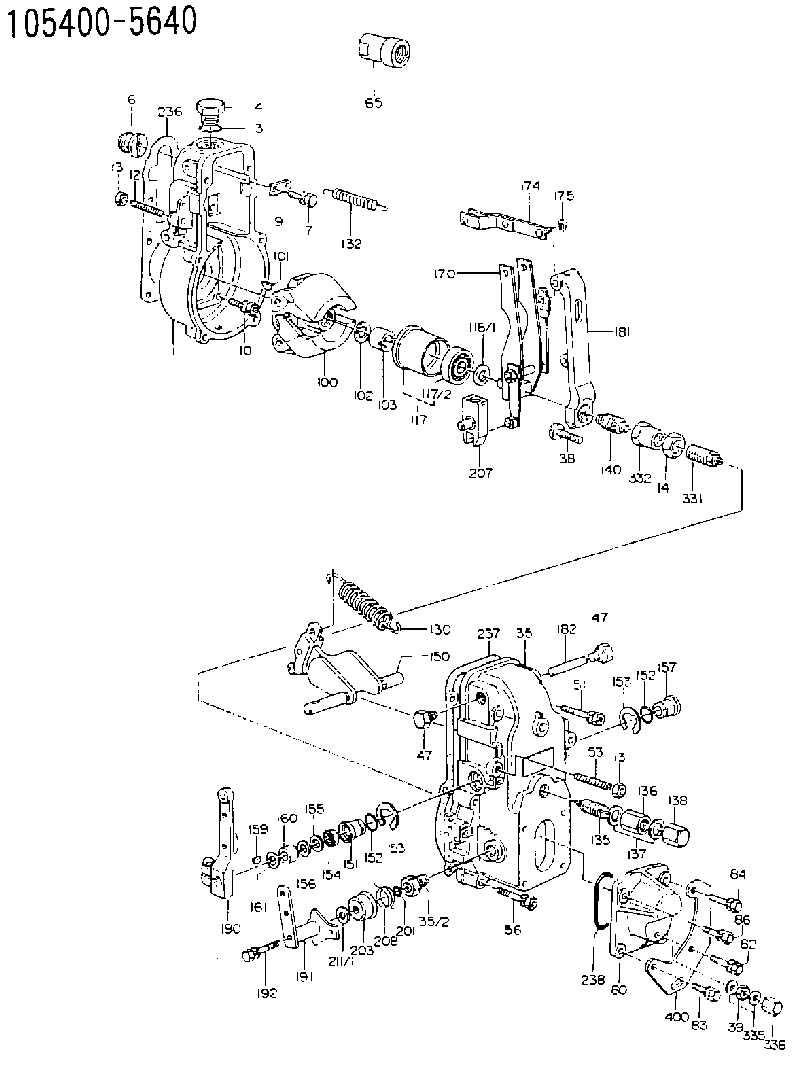
| 1. | [1] | 154000-6300 | GOVERNOR HOUSING |
| 3. | [1] | 029632-5070 | O-RING |
| 4. | [1] | 154007-2900 | CAPSULE |
| 6. | [1] | 154007-0200 | ADAPTOR |
| 7. | [1] | 020018-1840 | BLEEDER SCREW M8P1.25L18 |
| 9. | [1] | 154350-1900 | PLATE |
| 10. | [6] | 029010-6810 | BLEEDER SCREW |
| 12. | [1] | 154010-0100 | FLAT-HEAD SCREW |
| 13. | [2] | 154011-0100 | HEXAGON NUT |
| 13. | [2] | 154011-0100 | HEXAGON NUT |
| 35. | [1] | 154500-1020 | GOVERNOR COVER |
| 35/2. | [1] | 154321-0400 | BUSHING |
| 38. | [1] | 154031-3000 | FLAT-HEAD SCREW |
| 39. | [1] | 139206-0600 | UNION NUT |
| 47. | [2] | 154036-0300 | CAPSULE |
| 47. | [2] | 154036-0300 | CAPSULE |
| 51. | [2] | 020106-5040 | BLEEDER SCREW |
| 53. | [1] | 154010-0200 | FLAT-HEAD SCREW |
| 56. | [4] | 020106-3840 | BLEEDER SCREW |
| 65. | [1] | 154050-6120 | STOPPING DEVICE |
| 80. | [1] | 154063-5100 | COVER |
| 82. | [1] | 029020-6260 | BLEEDER SCREW |
| 83. | [1] | 029020-6260 | BLEEDER SCREW |
| 84. | [1] | 020006-2040 | BLEEDER SCREW M6P1L20 4T |
| 86. | [1] | 020006-1640 | BLEEDER SCREW M6P1L16 4T |
| 100. | [1] | 154101-0520 | FLYWEIGHT |
| 101. | [1] | 025803-1610 | WOODRUFF KEY |
| 102. | [1] | 029321-2020 | LOCKING WASHER |
| 103. | [1] | 029231-2030 | UNION NUT |
| 117. | [1] | 154123-0120 | SLIDING PIECE |
| 118/1. | [0] | 029311-0010 | SHIM D14&10.1T0.2 |
| 118/1. | [0] | 029311-0180 | SHIM D14&10.1T0.3 |
| 118/1. | [0] | 029311-0190 | SHIM D14&10.1T0.40 |
| 118/1. | [0] | 029311-0210 | SHIM D14&10.1T1 |
| 118/1. | [0] | 139410-0000 | SHIM D14.0&10.1T0.5 |
| 118/1. | [0] | 139410-0100 | SHIM D14.0&10.1T1.5 |
| 118/1. | [0] | 139410-3000 | SHIM D14&10.1T2.0 |
| 118/1. | [0] | 139410-3100 | SHIM D14&10.1T3.0 |
| 118/1. | [0] | 139410-3200 | SHIM D14&10.1T4.0 |
| 130. | [1] | 154150-2700 | GOVERNOR SPRING |
| 132. | [1] | 154154-0701 | COILED SPRING |
| 135. | [1] | 154158-0920 | HEADLESS SCREW |
| 136. | [1] | 154011-1700 | UNION NUT |
| 137. | [2] | 026512-1540 | GASKET D15.4&12.2T1.50 |
| 138. | [1] | 154159-1200 | CAP NUT |
| 140. | [1] | 154185-3620 | HEADLESS SCREW |
| 141. | [1] | 029201-6080 | UNION NUT |
| 150. | [1] | 154200-7120 | SWIVELLING LEVER |
| 151. | [1] | 154204-4300 | BUSHING |
| 152. | [2] | 029631-8020 | O-RING |
| 152. | [2] | 029631-8020 | O-RING |
| 153. | [2] | 016010-1640 | LOCKING WASHER |
| 153. | [2] | 016010-1640 | LOCKING WASHER |
| 154. | [1] | 139611-0000 | PACKING RING |
| 155. | [1] | 139411-0000 | SHIM |
| 156. | [0] | 029311-1070 | SHIM D16&11T0.5 |
| 157. | [1] | 154204-4400 | BUSHING |
| 159. | [1] | 025803-1310 | WOODRUFF KEY |
| 160. | [1] | 154206-2800 | BUSHING |
| 161. | [0] | 154206-0200 | PLAIN WASHER D19.5&11.2T1.0 |
| 170. | [1] | 154210-7320 | FORK LEVER |
| 174. | [1] | 154230-3920 | STRAP |
| 175. | [1] | 016010-0540 | LOCKING WASHER |
| 181. | [1] | 154236-1500 | TENSIONING LEVER |
| 182. | [1] | 154237-0100 | BEARING PIN |
| 190. | [1] | 154309-6120 | CONTROL LEVER |
| 191. | [1] | 154365-9321 | CONTROL LEVER |
| 192. | [1] | 020006-4540 | BLEEDER SCREW M6P1L45 |
| 201. | [1] | 029631-0030 | O-RING &9.8W2.3 |
| 203. | [1] | 154322-0100 | CAP |
| 207. | [1] | 154326-5020 | CONTROL LEVER |
| 208. | [1] | 154327-7600 | COILED SPRING |
| 211/1. | [0] | 029311-0520 | SHIM D20.8&10.3T0.2 |
| 211/1. | [0] | 029311-0530 | SHIM D20.8&10.3T0.25 |
| 211/1. | [0] | 029311-0540 | SHIM D20.8&10.3T0.3 |
| 211/1. | [0] | 029311-0550 | SHIM D20.8&10.3T0.35 |
| 211/1. | [0] | 029311-0560 | SHIM D20.8&10.3T0.4 |
| 211/1. | [0] | 029311-0570 | SHIM D20.8&10.3T0.5 |
| 236. | [1] | 154390-0000 | GASKET |
| 237. | [1] | 154390-0300 | GASKET |
| 238. | [1] | 029635-2020 | O-RING |
| 331. | [1] | 154179-0220 | HEADLESS SCREW |
| 332. | [1] | 029201-6010 | UNION NUT |
| 335. | [2] | 026506-1040 | GASKET D9.9&6.2T1 |
| 336. | [1] | 154035-1600 | CAP NUT |
| 400. | [1] | 154358-7200 | BRACKET |
Include in #1:
101492-9200
as GOVERNOR
Cross reference number
Zexel num
Bosch num
Firm num
Name
105400-5640
1910990269 NISSAN-DIESEL
GOVERNOR
K 14JB MECHANICAL GOVERNOR GOV RSV GOV
K 14JB MECHANICAL GOVERNOR GOV RSV GOV
Information:
Keep all parts clean from contaminants. Contaminants put into the system may cause rapid wear and shortened component life.
1. Remove bolts (1) and rocker shaft assembly (2). Remove the O-ring seal from the rear rocker arm support bracket.2. Put identification marks on push rods (3) as to their location in the engine. Remove the push rods. The following steps are for the installation of the rocker shaft assembly and push rods.3. Loosen the adjusting screws (4). This will prevent a bent valve or push rod during installation of the rocker shaft assembly. Install push rods (3). The O-ring seal in the rear support must be installed new each time the bolt is removed from the rear support bracket.4. Install rocker shaft assembly (2).
Make sure the dowels on each end of the rocker shaft assembly are in alignment with the holes in the cylinder head.
5. Put 2P2506 Thread Lubricant on all of bolts (1) except for bolt (10) that goes through the rear rocker arm support bracket. Install the bolts in the rocker shaft assembly.6. Tighten bolts (1) for the rocker shaft as follows: a. Tighten all the bolts in number sequence to a torque of 155 N m (115 lb ft).b. Tighten all the bolts again in number sequence to a torque of 250 17 N m (185 13 lb ft).c. Last, tighten bolts again in number sequence (hand tighten only to a torque of 250 17 N m (185 13 lb ft).7. The assembled length of springs at both ends of rocker shaft must be 1.50 0.25 mm (.059 .010 in). Remove or install washers behind springs to change the assembled length of the springs.8. Make adjustments until the intake valve clearance is .038 mm (.015 in) and the exhaust valve clearance is 0.64 mm (.025 in). See the topic, Valve Clearance Setting, in Testing And Adjusting. Tighten the locknuts (2) for the adjusting screws (1) to a torque of 29 7 N m (21 5 lb ft).End By:a. install valve cover.Disassemble And Assemble Rocker Shaft
Start By:a. remove rocker shaft and push rods
Keep all parts clean from contaminants. Contaminants put into the system may cause rapid wear and shortened component life.
1. Remove O-ring seal (1). A replacement of the O-ring seal must be made each time the head bolt is removed from the rear support bracket. 2. Remove retainer ring (6), washer (5), spring (4) washer (3) and rocker arm (2). 3. Remove pin from rear support bracket with a hammer and punch. Remove rear support bracket (7).4. Remove remainder of rocker arms, springs, washers and brackets.5. Remove plugs from each end of the shaft if necessary. The following steps are for the assembly of the rocker shaft. 6. Install rocker arms (2), brackets (8), washers (5) and springs (4) on the rocker shaft.7. Install rear support bracket (7). Make sure the hole in rear support bracket is in alignment with the hole in rocker shaft.8. Install pin (9)