Information governor
BOSCH
9 420 612 497
9420612497
ZEXEL
105400-5631
1054005631
ISUZU
8943622610
8943622610

Rating:
Scheme ###:
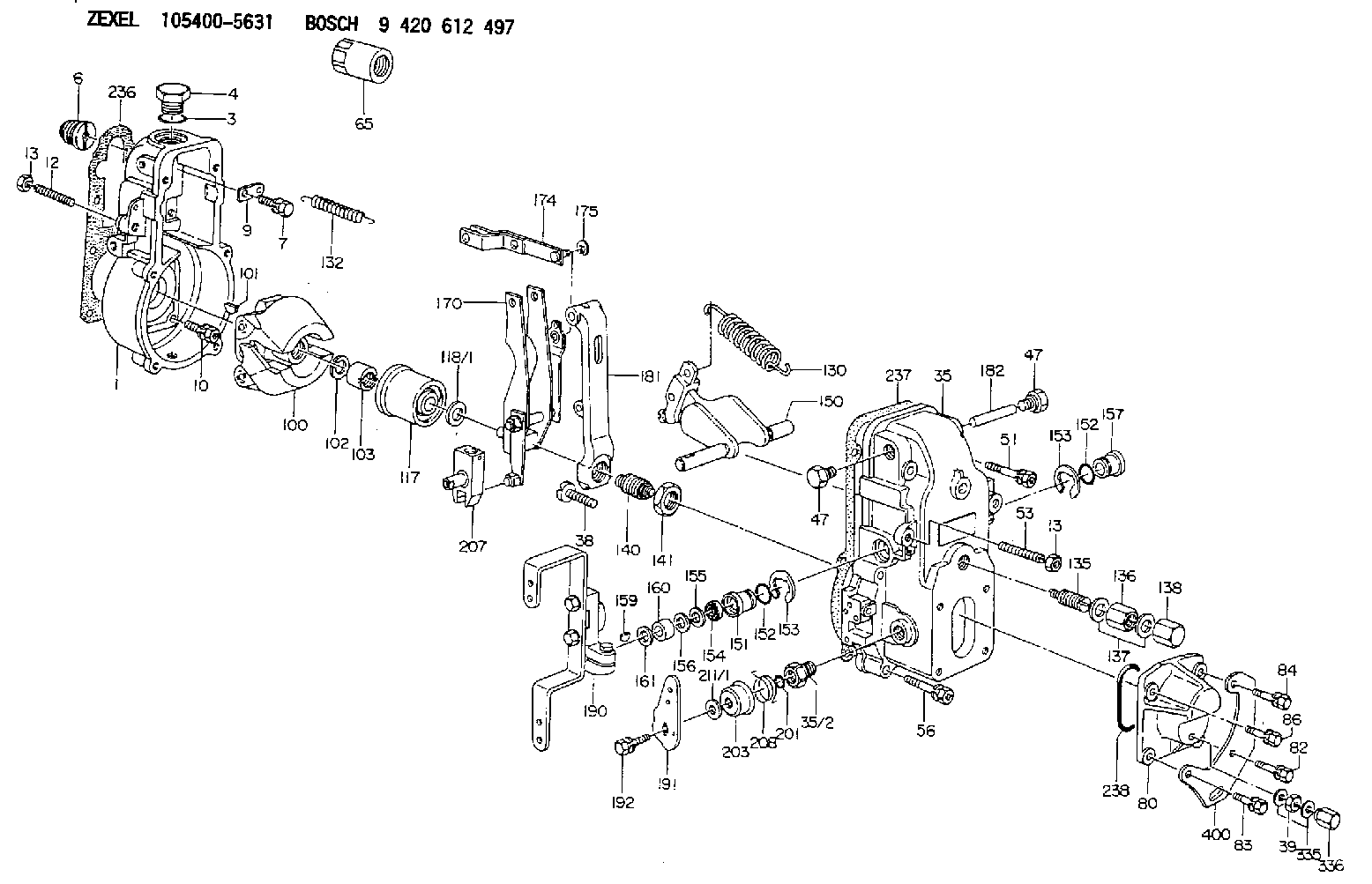
| 1. | [1] | 154000-6300 | GOVERNOR HOUSING |
| 3. | [1] | 029632-5070 | O-RING |
| 4. | [1] | 154007-2900 | CAPSULE |
| 6. | [1] | 154007-0200 | ADAPTOR |
| 7. | [1] | 020018-1840 | BLEEDER SCREW M8P1.25L18 |
| 9. | [1] | 154350-1900 | PLATE |
| 10. | [6] | 029010-6810 | BLEEDER SCREW |
| 12. | [1] | 154010-0100 | FLAT-HEAD SCREW |
| 13. | [2] | 154011-0100 | HEXAGON NUT |
| 13. | [2] | 154011-0100 | HEXAGON NUT |
| 35. | [1] | 154500-1020 | GOVERNOR COVER |
| 35/2. | [1] | 154321-0400 | BUSHING |
| 38. | [1] | 154031-3000 | FLAT-HEAD SCREW |
| 39. | [1] | 139206-0600 | UNION NUT |
| 47. | [2] | 154036-0300 | CAPSULE |
| 47. | [2] | 154036-0300 | CAPSULE |
| 51. | [2] | 020106-5040 | BLEEDER SCREW |
| 53. | [1] | 154010-0200 | FLAT-HEAD SCREW |
| 56. | [4] | 020106-3840 | BLEEDER SCREW |
| 65. | [1] | 155404-5700 | CAP |
| 80. | [1] | 154063-5100 | COVER |
| 82. | [1] | 029020-6260 | BLEEDER SCREW |
| 83. | [1] | 029020-6260 | BLEEDER SCREW |
| 84. | [1] | 020006-2040 | BLEEDER SCREW M6P1L20 4T |
| 86. | [1] | 020006-1640 | BLEEDER SCREW M6P1L16 4T |
| 100. | [1] | 154101-0020 | FLYWEIGHT ASSEMBLY |
| 101. | [1] | 025803-1610 | WOODRUFF KEY |
| 102. | [1] | 029321-2020 | LOCKING WASHER |
| 103. | [1] | 029231-2030 | UNION NUT |
| 117. | [1] | 154123-2320 | SLIDING PIECE |
| 118/1. | [0] | 029311-0010 | SHIM D14&10.1T0.2 |
| 118/1. | [0] | 029311-0180 | SHIM D14&10.1T0.3 |
| 118/1. | [0] | 029311-0190 | SHIM D14&10.1T0.40 |
| 118/1. | [0] | 029311-0210 | SHIM D14&10.1T1 |
| 118/1. | [0] | 139410-0000 | SHIM D14.0&10.1T0.5 |
| 118/1. | [0] | 139410-0100 | SHIM D14.0&10.1T1.5 |
| 118/1. | [0] | 139410-3000 | SHIM D14&10.1T2.0 |
| 118/1. | [0] | 139410-3100 | SHIM D14&10.1T3.0 |
| 118/1. | [0] | 139410-3200 | SHIM D14&10.1T4.0 |
| 130. | [1] | 154150-0100 | GOVERNOR SPRING |
| 132. | [1] | 154154-0800 | COILED SPRING |
| 135. | [1] | 154158-0820 | HEADLESS SCREW |
| 136. | [1] | 154011-1700 | UNION NUT |
| 137. | [2] | 026512-1540 | GASKET D15.4&12.2T1.50 |
| 138. | [1] | 154159-1200 | CAP NUT |
| 140. | [1] | 154178-9220 | HEADLESS SCREW |
| 141. | [1] | 029201-6010 | UNION NUT |
| 150. | [1] | 154200-0220 | SWIVELLING LEVER |
| 151. | [2] | 154204-1900 | BUSHING |
| 152. | [2] | 029631-8020 | O-RING |
| 152. | [2] | 029631-8020 | O-RING |
| 153. | [2] | 016010-1640 | LOCKING WASHER |
| 153. | [2] | 016010-1640 | LOCKING WASHER |
| 154. | [1] | 139611-0000 | PACKING RING |
| 155. | [1] | 139411-0000 | SHIM |
| 156. | [0] | 029311-1090 | SHIM D16&11T0.3 |
| 157. | [1] | 029141-7010 | CAPSULE |
| 159. | [1] | 025803-1310 | WOODRUFF KEY |
| 160. | [1] | 154206-2800 | BUSHING |
| 161. | [0] | 154206-0200 | PLAIN WASHER D19.5&11.2T1.0 |
| 170. | [1] | 154210-7320 | FORK LEVER |
| 174. | [1] | 154230-3920 | STRAP |
| 175. | [1] | 016010-0540 | LOCKING WASHER |
| 181. | [1] | 154236-4100 | TENSIONING LEVER |
| 182. | [1] | 154237-0100 | BEARING PIN |
| 190. | [1] | 154343-4920 | CONTROL LEVER |
| 191. | [1] | 154365-7900 | CONTROL LEVER |
| 192. | [1] | 020006-1640 | BLEEDER SCREW M6P1L16 4T |
| 201. | [1] | 029631-0030 | O-RING &9.8W2.3 |
| 203. | [1] | 154322-0100 | CAP |
| 207. | [1] | 154326-5020 | CONTROL LEVER |
| 208. | [1] | 154327-7600 | COILED SPRING |
| 211/1. | [0] | 029311-0520 | SHIM D20.8&10.3T0.2 |
| 211/1. | [0] | 029311-0530 | SHIM D20.8&10.3T0.25 |
| 211/1. | [0] | 029311-0540 | SHIM D20.8&10.3T0.3 |
| 211/1. | [0] | 029311-0550 | SHIM D20.8&10.3T0.35 |
| 211/1. | [0] | 029311-0560 | SHIM D20.8&10.3T0.4 |
| 211/1. | [0] | 029311-0570 | SHIM D20.8&10.3T0.5 |
| 236. | [1] | 154390-0000 | GASKET |
| 237. | [1] | 154390-0300 | GASKET |
| 238. | [1] | 029635-2020 | O-RING |
| 335. | [2] | 026506-1040 | GASKET D9.9&6.2T1 |
| 336. | [1] | 154035-1600 | CAP NUT |
| 400. | [1] | 154358-7200 | BRACKET |
Include in #1:
101492-0383
as GOVERNOR
Cross reference number
Zexel num
Bosch num
Firm num
Name
Information:
Keep all parts clean from contaminants. Contaminants put into the system may cause rapid wear and shortened component life.
1. Install the turbocharger on tool (A) as shown.2. Put alignment marks on three housings of the turbocharger for correct alignment during assembly. Loosen clamp (2), and remove the clamp and housing (1) from housing assembly (3). 3. Loosen clamp (4), and remove housing assembly (3) from housing (5). 4. Put the cartridge group in position in tool (B) as shown.
When the nut is loosened, do not put a side force on the shaft. This can result in a bent shaft.
5. Use a 5S9566 Sliding T-Wrench and a universal socket (6) to remove the nut that holds the compressor wheel to the wheel assembly.6. Remove compressor wheel (7) and the shims from wheel assembly (8).7. Remove housing assembly (3). 8. Remove ring (9) and backplate (10). 9. Use tool (C), and remove snap ring (11). 10. Remove insert (12) and sleeve (13). 11. Remove ring (14). 12. Remove two screws (15) and deflector (16). 13. Remove ring (18) and bearing assembly (17). 14. Remove sleeve (19) and ring (20). 15. Remove O-ring seal (23). Use tool (D), and remove snap ring (22).16. Remove bearing (21). Remove the snap ring behind the bearing with tool (D). 17. Use tool (D), and remove snap ring (25). Remove bearing (24). Remove the snap ring behind the bearing with tool (D).18. Check all the parts of the turbocharger for damage. If the parts are damaged, use new parts for replacement. See Special Instruction, Form No. SMHS6854, for Turbocharger Reconditioning. Also, see Guidelines For Reusable Parts, Form No. SEBF8018.Assemble Turbocharger (Schwitzer S4A)
1. Make sure that all of the oil passages in the turbocharger cartridge housing are clean and free of dirt and foreign material. Do not put oil on any parts of the turbocharger until after the compressor wheel has been installed. After the turbocharger has been assembled, pour clean engine oil into the oil inlet of the turbocharger.
Make sure that the snap rings that hold bearings (24) and (21) in position in housing assembly (3) are installed with the round edge of the outside diameter toward the bearing.
2. Install the snap ring behind bearing (24) with tool (D). Install bearing (24).3. Use tool (D), and install snap ring (25). 4. Install the snap ring behind bearing (21) with tool (D). Install bearing (21).5. Use tool (D), and install snap ring (22). 6. Put wheel assembly (8) in position on tool (B) as shown. Put backplate (10) in position on the wheel assembly. Put 6V2055 High Vacuum Grease in the groove for seal ring (9) at assembly to one half or more of the depth of the groove all the way around.7. Install ring (9) in the groove in wheel assembly (8). 8. Install housing assembly (3) on wheel assembly (8). 9. Install ring (20) and sleeve (13). 10. Make sure the screen is in place in bearing assembly (17). 11. Install bearing assembly (17)