Information governor
BOSCH
F 019 Z1E 569
f019z1e569
ZEXEL
105400-5340
1054005340
NISSAN-DIESEL
1910990264
1910990264
Rating:
Scheme ###:
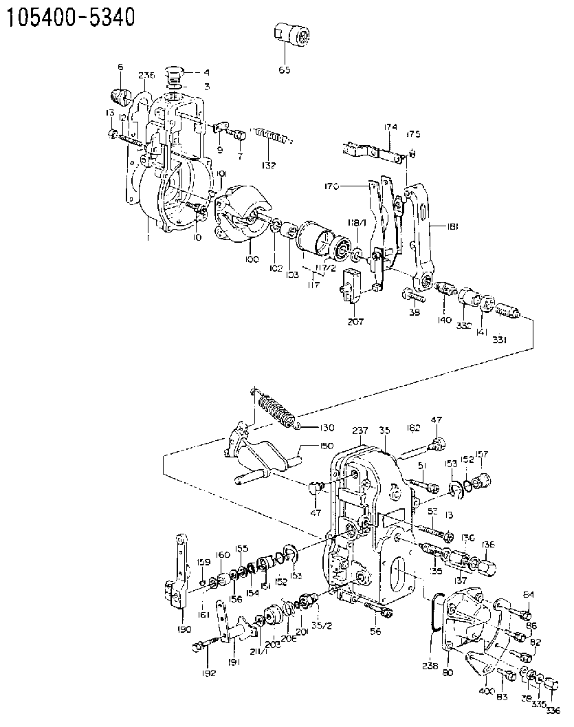
| 1. | [1] | 154000-6300 | GOVERNOR HOUSING |
| 3. | [1] | 029632-5070 | O-RING |
| 4. | [1] | 154007-2900 | CAPSULE |
| 6. | [1] | 154007-0200 | ADAPTOR |
| 7. | [1] | 020018-1840 | BLEEDER SCREW M8P1.25L18 |
| 9. | [1] | 154350-1900 | PLATE |
| 10. | [6] | 029010-6810 | BLEEDER SCREW |
| 12. | [1] | 154010-0100 | FLAT-HEAD SCREW |
| 13. | [2] | 154011-0100 | HEXAGON NUT |
| 13. | [2] | 154011-0100 | HEXAGON NUT |
| 35. | [1] | 154500-1020 | GOVERNOR COVER |
| 35/2. | [1] | 154321-0400 | BUSHING |
| 38. | [1] | 154031-3000 | FLAT-HEAD SCREW |
| 39. | [1] | 139206-0600 | UNION NUT |
| 47. | [2] | 154036-0300 | CAPSULE |
| 47. | [2] | 154036-0300 | CAPSULE |
| 51. | [2] | 020106-5040 | BLEEDER SCREW |
| 53. | [1] | 154010-0200 | FLAT-HEAD SCREW |
| 56. | [4] | 020106-3840 | BLEEDER SCREW |
| 65. | [1] | 154050-1720 | STOPPING DEVICE |
| 80. | [1] | 154063-5100 | COVER |
| 82. | [1] | 029020-6260 | BLEEDER SCREW |
| 83. | [1] | 029020-6260 | BLEEDER SCREW |
| 84. | [1] | 020006-2040 | BLEEDER SCREW M6P1L20 4T |
| 86. | [1] | 020006-1640 | BLEEDER SCREW M6P1L16 4T |
| 100. | [1] | 154101-0520 | FLYWEIGHT |
| 101. | [1] | 025803-1610 | WOODRUFF KEY |
| 102. | [1] | 029321-2020 | LOCKING WASHER |
| 103. | [1] | 029231-2030 | UNION NUT |
| 117. | [1] | 154123-0120 | SLIDING PIECE |
| 118/1. | [0] | 029311-0010 | SHIM D14&10.1T0.2 |
| 118/1. | [0] | 029311-0180 | SHIM D14&10.1T0.3 |
| 118/1. | [0] | 029311-0190 | SHIM D14&10.1T0.40 |
| 118/1. | [0] | 029311-0210 | SHIM D14&10.1T1 |
| 118/1. | [0] | 139410-0000 | SHIM D14.0&10.1T0.5 |
| 118/1. | [0] | 139410-0100 | SHIM D14.0&10.1T1.5 |
| 118/1. | [0] | 139410-3000 | SHIM D14&10.1T2.0 |
| 118/1. | [0] | 139410-3100 | SHIM D14&10.1T3.0 |
| 118/1. | [0] | 139410-3200 | SHIM D14&10.1T4.0 |
| 130. | [1] | 154150-2700 | GOVERNOR SPRING |
| 132. | [1] | 154154-0701 | COILED SPRING |
| 135. | [1] | 154158-0920 | HEADLESS SCREW |
| 136. | [1] | 154011-1700 | UNION NUT |
| 137. | [2] | 026512-1540 | GASKET D15.4&12.2T1.50 |
| 138. | [1] | 154159-1200 | CAP NUT |
| 140. | [1] | 154185-1320 | HEADLESS SCREW |
| 141. | [1] | 029201-6080 | UNION NUT |
| 150. | [1] | 154200-7120 | SWIVELLING LEVER |
| 151. | [1] | 154204-4300 | BUSHING |
| 152. | [2] | 029631-8020 | O-RING |
| 152. | [2] | 029631-8020 | O-RING |
| 153. | [2] | 016010-1640 | LOCKING WASHER |
| 153. | [2] | 016010-1640 | LOCKING WASHER |
| 154. | [1] | 139611-0000 | PACKING RING |
| 155. | [1] | 139411-0000 | SHIM |
| 156. | [0] | 029311-1070 | SHIM D16&11T0.5 |
| 157. | [1] | 154204-4400 | BUSHING |
| 159. | [1] | 025803-1310 | WOODRUFF KEY |
| 160. | [1] | 154206-2800 | BUSHING |
| 161. | [0] | 154206-0200 | PLAIN WASHER D19.5&11.2T1.0 |
| 170. | [1] | 154210-7320 | FORK LEVER |
| 174. | [1] | 154230-3920 | STRAP |
| 175. | [1] | 016010-0540 | LOCKING WASHER |
| 181. | [1] | 154236-1500 | TENSIONING LEVER |
| 182. | [1] | 154237-0100 | BEARING PIN |
| 190. | [1] | 154309-6120 | CONTROL LEVER |
| 191. | [1] | 154365-9321 | CONTROL LEVER |
| 192. | [1] | 020006-4540 | BLEEDER SCREW M6P1L45 |
| 201. | [1] | 029631-0030 | O-RING &9.8W2.3 |
| 203. | [1] | 154322-0100 | CAP |
| 207. | [1] | 154326-5020 | CONTROL LEVER |
| 208. | [1] | 154327-7600 | COILED SPRING |
| 211/1. | [0] | 029311-0520 | SHIM D20.8&10.3T0.2 |
| 211/1. | [0] | 029311-0530 | SHIM D20.8&10.3T0.25 |
| 211/1. | [0] | 029311-0540 | SHIM D20.8&10.3T0.3 |
| 211/1. | [0] | 029311-0550 | SHIM D20.8&10.3T0.35 |
| 211/1. | [0] | 029311-0560 | SHIM D20.8&10.3T0.4 |
| 211/1. | [0] | 029311-0570 | SHIM D20.8&10.3T0.5 |
| 236. | [1] | 154390-0000 | GASKET |
| 237. | [1] | 154390-0300 | GASKET |
| 238. | [1] | 029635-2020 | O-RING |
| 331. | [1] | 154179-2220 | HEADLESS SCREW |
| 332. | [1] | 029201-6010 | UNION NUT |
| 335. | [2] | 026506-1040 | GASKET D9.9&6.2T1 |
| 336. | [1] | 154035-1600 | CAP NUT |
| 400. | [1] | 154358-7200 | BRACKET |
Include in #1:
101492-9160
as GOVERNOR
Cross reference number
Zexel num
Bosch num
Firm num
Name
105400-5340
1910990264 NISSAN-DIESEL
GOVERNOR
K 14JB MECHANICAL GOVERNOR GOV RSV GOV
K 14JB MECHANICAL GOVERNOR GOV RSV GOV
Information:
Make reference to Analyzing Turbocharger Failure, Form No. FEG45138.(1) See Turbocharger Impeller Installation.(2) Torque for the bolts that hold back plate ... 10.2 1.1 N m (90 10 lb in)(3) Torque for the clamp bolts ... 13.6 1.1 N m (120 10 lb in)(4) Bore in the bearings ... 15.921 to 15.931 mm (.6268 to .6272 in) Diameter of the surface on the shaft for the bearings ... 15.875 to 15.885 mm (.6250 to .6254 in)(5) Bore in the housing ... 24.961 to 24.973 mm (.9827 to .9832 in) Outside diameter of the bearing ... 24.846 to 24.859 mm (.9782 to .9787 in)(6) Clearance between the ends of the oil seal ring ... 0.20 to 0.38 mm (.008 to .015 in)(7) End play for the shaft ... 0.08 to 0.25 mm (.003 to .010 in)(8) Put 5P3931 Anti-Seize Compound on the threads and tighten the bolts that hold the turbocharger to the manifold to a torque of ... 55 5 N m (40 4 lb ft)Schwitzer (S4A)
(1) End play for shaft (new) ... 0.114 0.038 mm(.0045 .0015 in) Maximum permissible end play (worn) ... 0.20 mm (.008 in)(2) Thickness of thrust bearing (where thrust rings contact bearing) ... 5.36 0.03 mm (.211 .001 in)(3) Tighten both band clamps with procedure that follows: a. Tighten to ... 14 1.1 N m (125 10 lb in)b. Tap (hit) clamp lightly all around.c. Tighten again to ... 14 1.1 N m (125 10 lb in)
Do not overtighten the clamps.
(4) Diameter of shaft (new) ... 15.997 to 16.005 mm (.6298 to .6301 in) Bore in the bearing (new) ... 16.035 to 16.043 mm (.6313 to .6316 in)Maximum permissible clearance between bearing and shaft (worn) ... 0.05 mm (.002 in)(5) Maximum permissible gap of oil seal ring, measured in bore of housing ... 0.25 mm (.010 in)(6) Install the compressor wheel (at room temperature) as follows: a. See Compressor Wheel Clearance for the correct shim thickness to use.b. Put compressor wheel on the shaft.c. Put a small amount of clean engine oil on the threads.d. Tighten the nut to 14 to 17 N m (125 to 150 lb in).
Do not bend or add stress to the shaft when nut is loosened or tightened.
e. Remove nut from shaft and apply 6V1541 Quick Cure Primer on the threads of the shaft and nut followed by application of 9S3265 Retaining Compound.f. Tighten nut to 4 N m (30 lb in).g. Tighten nut more as follows: For 99.0 mm (3.90 in) diameter compressor wheels, tighten the nut an additional 90°.For 86.4 mm (3.40 in) diameter compressor wheels, tighten the nut an additional 60°.(7) Shims. See Compressor Wheel Clearance for the correct shim thickness to use.(8) Thickness of each thrust ring ... 2.553 0.013 mm (.1005 .0005 in)(9) Bore in housing (new) ... 24.994 to 25.006 mm (.9840 to .9845 in) Outside diameter of the bearing (new) ... 24.882 to 24.892 mm