Information governor
BOSCH
F 019 Z4E 194
f019z4e194
ZEXEL
105400-5100
1054005100
MITSUBISHI
ME723150
me723150
Rating:
Scheme ###:
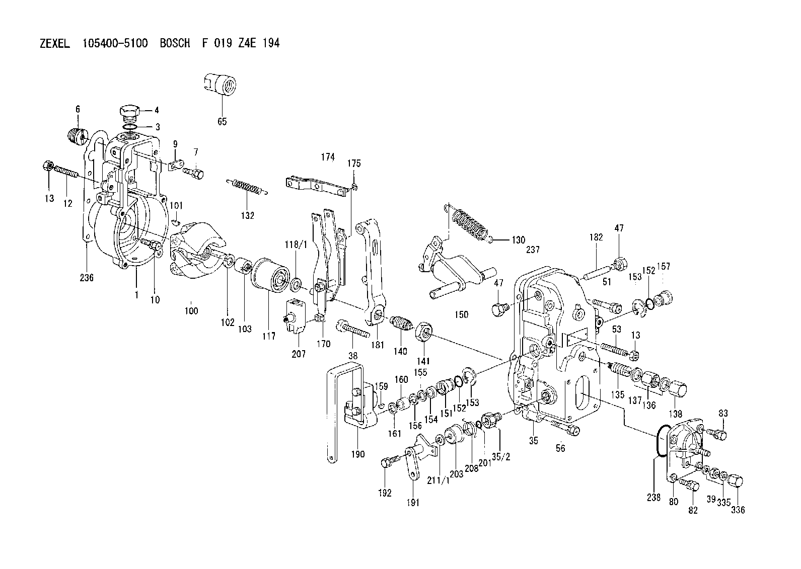
| 1. | [1] | 154000-6300 | GOVERNOR HOUSING |
| 3. | [1] | 029632-5070 | O-RING |
| 4. | [1] | 154007-2900 | CAPSULE |
| 6. | [1] | 154007-0200 | ADAPTOR |
| 7. | [1] | 020018-1840 | BLEEDER SCREW M8P1.25L18 |
| 9. | [1] | 154350-1900 | PLATE |
| 10. | [6] | 029010-6810 | BLEEDER SCREW |
| 12. | [1] | 154010-0100 | FLAT-HEAD SCREW |
| 13. | [2] | 154011-0100 | HEXAGON NUT |
| 13. | [2] | 154011-0100 | HEXAGON NUT |
| 35. | [1] | 154500-1020 | GOVERNOR COVER |
| 35/2. | [1] | 154321-0400 | BUSHING |
| 38. | [1] | 154031-2400 | FLAT-HEAD SCREW |
| 39. | [1] | 139206-0600 | UNION NUT |
| 47. | [2] | 154036-0300 | CAPSULE |
| 47. | [2] | 154036-0300 | CAPSULE |
| 51. | [2] | 020106-5040 | BLEEDER SCREW |
| 53. | [1] | 154010-0200 | FLAT-HEAD SCREW |
| 56. | [4] | 020106-3840 | BLEEDER SCREW |
| 65. | [1] | 154050-6120 | STOPPING DEVICE |
| 80. | [1] | 154063-5420 | COVER |
| 82. | [2] | 029020-6210 | BLEEDER SCREW |
| 83. | [2] | 020006-1640 | BLEEDER SCREW M6P1L16 4T |
| 100. | [1] | 154101-0120 | FLYWEIGHT |
| 101. | [1] | 025803-1610 | WOODRUFF KEY |
| 102. | [1] | 029321-2020 | LOCKING WASHER |
| 103. | [1] | 029231-2030 | UNION NUT |
| 117. | [1] | 154123-2320 | SLIDING PIECE |
| 118/1. | [0] | 029311-0010 | SHIM D14&10.1T0.2 |
| 118/1. | [0] | 029311-0180 | SHIM D14&10.1T0.3 |
| 118/1. | [0] | 029311-0190 | SHIM D14&10.1T0.40 |
| 118/1. | [0] | 029311-0210 | SHIM D14&10.1T1 |
| 118/1. | [0] | 139410-0000 | SHIM D14.0&10.1T0.5 |
| 118/1. | [0] | 139410-0100 | SHIM D14.0&10.1T1.5 |
| 118/1. | [0] | 139410-3000 | SHIM D14&10.1T2.0 |
| 118/1. | [0] | 139410-3100 | SHIM D14&10.1T3.0 |
| 118/1. | [0] | 139410-3200 | SHIM D14&10.1T4.0 |
| 130. | [1] | 154150-2900 | GOVERNOR SPRING |
| 132. | [1] | 154154-0500 | COILED SPRING |
| 135. | [1] | 154158-2320 | HEADLESS SCREW |
| 136. | [1] | 154011-1700 | UNION NUT |
| 137. | [2] | 026512-1540 | GASKET D15.4&12.2T1.50 |
| 138. | [1] | 154159-1200 | CAP NUT |
| 140. | [1] | 154177-2320 | HEADLESS SCREW |
| 141. | [1] | 029201-6010 | UNION NUT |
| 150. | [1] | 154200-7020 | SWIVELLING LEVER |
| 151. | [1] | 154204-4300 | BUSHING |
| 152. | [2] | 029631-8020 | O-RING |
| 152. | [2] | 029631-8020 | O-RING |
| 153. | [2] | 016010-1640 | LOCKING WASHER |
| 153. | [2] | 016010-1640 | LOCKING WASHER |
| 154. | [1] | 139611-0000 | PACKING RING |
| 155. | [1] | 139411-0000 | SHIM |
| 156. | [0] | 029311-1070 | SHIM D16&11T0.5 |
| 157. | [1] | 154204-4400 | BUSHING |
| 159. | [1] | 025803-1310 | WOODRUFF KEY |
| 160. | [1] | 154206-2800 | BUSHING |
| 161. | [0] | 154206-0200 | PLAIN WASHER D19.5&11.2T1.0 |
| 170. | [1] | 154210-0920 | FORK LEVER |
| 174. | [1] | 154230-3920 | STRAP |
| 175. | [1] | 016010-0540 | LOCKING WASHER |
| 181. | [1] | 154236-4100 | TENSIONING LEVER |
| 182. | [1] | 154237-0100 | BEARING PIN |
| 190. | [1] | 154347-2920 | CONTROL LEVER |
| 191. | [1] | 154366-3720 | CONTROL LEVER |
| 192. | [1] | 020006-3540 | BLEEDER SCREW |
| 201. | [1] | 029631-0030 | O-RING &9.8W2.3 |
| 203. | [1] | 154322-0100 | CAP |
| 207. | [1] | 154326-5020 | CONTROL LEVER |
| 208. | [1] | 154327-7700 | COILED SPRING |
| 211/1. | [0] | 029311-0520 | SHIM D20.8&10.3T0.2 |
| 211/1. | [0] | 029311-0530 | SHIM D20.8&10.3T0.25 |
| 211/1. | [0] | 029311-0540 | SHIM D20.8&10.3T0.3 |
| 211/1. | [0] | 029311-0550 | SHIM D20.8&10.3T0.35 |
| 211/1. | [0] | 029311-0560 | SHIM D20.8&10.3T0.4 |
| 211/1. | [0] | 029311-0570 | SHIM D20.8&10.3T0.5 |
| 236. | [1] | 154390-0000 | GASKET |
| 237. | [1] | 154390-0300 | GASKET |
| 238. | [1] | 029635-2020 | O-RING |
| 335. | [2] | 026506-1040 | GASKET D9.9&6.2T1 |
| 336. | [1] | 154035-1600 | CAP NUT |
Include in #1:
101691-1981
as GOVERNOR
Cross reference number
Zexel num
Bosch num
Firm num
Name
Information:
4. Put clean engine oil on the O-ring seal, and assemble elbow (4) to drain tube (5).5. Put the gaskets in position on the block and on the turbocharger, and install the drain tube assembly. 6. Put a gasket in position between oil supply tube (6) and the turbocharger. Install oil supply tube (6).Disassemble Turbocharger (TV72 & TV78)
START BY:a. remove turbocharger (TV72 & TV78) 1. Install the turbocharger in tool group (A). Put alignment marks on the three housings of the turbocharger for correct installation and alignment at assembly. Remove "V" clamp (2) and compressor housing (1). 2. Remove "V" clamp (3). Remove cartridge housing (5) from turbine housing (4).
When the nut is loosened, do not put a side force on the shaft. This can result in a bent shaft.
3. Install tool (C) in tool (B), and put the cartridge assembly in tool (C) as shown. Use tool (D) to remove the nut that holds compressor wheel (6). 4. Put the cartridge assembly in tool (E), and use a press (if necessary) to remove compressor wheel (6) from the turbine wheel and shaft assembly. Do not let the turbine wheel and shaft assembly fall during removal of the compressor wheel from the turbine wheel and shaft. 5. Remove seal ring (7) and shroud (8) from turbine wheel and shaft assembly (9). 6. Bend the tabs of the locks from bolts (10), and remove the bolts and locks.7. Remove backplate assembly (11) from the cartridge housing. 8. Remove spacer (12) from backplate assembly (11). Remove seal rings (13) from spacer (12). 9. Remove collar (14), thrust bearing (15) and O-ring seal (16) from the cartridge housing. 10. Remove top bearing (17) and the washer from the cartridge housing. Put a long dye mark on the top face of bearing (17).11. Use tool (F), and remove the two rings that hold the top and bottom bearings in position. Remove the bottom bearing and washer. Put a short dye mark on the bearing. The dye marks are used for identification of the bearings when they are installed.12. Use tool (F), and remove the last ring that holds the bottom bearing in position from the cartridge housing.13. Check all the parts of the turbocharger for damage. If the parts are damaged, use new parts for replacement. See Special Instruction Form No. SMHS6854 for Turbocharger Reconditioning. Also see Guidelines For Reuseable Parts, Form No. SEBF8018.Assemble Turbocharger (TV72 & TV78)
1. Make sure that all of the oil passages in the turbocharger cartridge housing are clean and free of dirt and foreign material.2. Put clean engine oil on all parts of the cartridge assembly.
Rings (1), (4) and (5) must be installed with the round edge of the outside diameter of the rings toward the bearings.
3. Install ring (4) in the cartridge