Information governor
BOSCH
F 019 Z4E 193
f019z4e193
ZEXEL
105400-5060
1054005060
ISUZU
8943377780
8943377780
Rating:
Scheme ###:
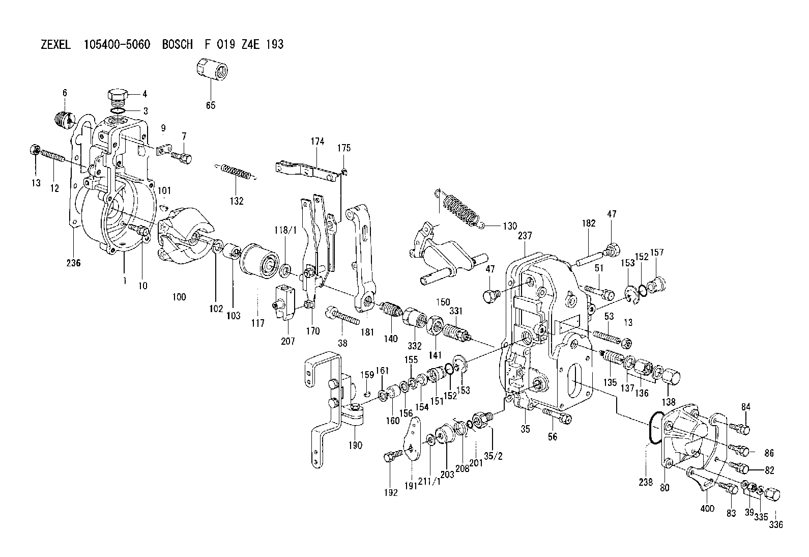
| 1. | [1] | 154000-6300 | GOVERNOR HOUSING |
| 3. | [1] | 029632-5070 | O-RING |
| 4. | [1] | 154007-2900 | CAPSULE |
| 6. | [1] | 154007-0200 | ADAPTOR |
| 7. | [1] | 020018-1840 | BLEEDER SCREW M8P1.25L18 |
| 9. | [1] | 154350-1900 | PLATE |
| 10. | [6] | 029010-6810 | BLEEDER SCREW |
| 12. | [1] | 154010-1100 | FLAT-HEAD SCREW |
| 13. | [2] | 154011-0100 | HEXAGON NUT |
| 13. | [2] | 154011-0100 | HEXAGON NUT |
| 35. | [1] | 154500-1020 | GOVERNOR COVER |
| 35/2. | [1] | 154321-0400 | BUSHING |
| 38. | [1] | 154031-3000 | FLAT-HEAD SCREW |
| 39. | [1] | 139206-0600 | UNION NUT |
| 47. | [2] | 154036-0300 | CAPSULE |
| 47. | [2] | 154036-0300 | CAPSULE |
| 51. | [2] | 020106-5040 | BLEEDER SCREW |
| 53. | [1] | 154010-0200 | FLAT-HEAD SCREW |
| 56. | [4] | 020106-3840 | BLEEDER SCREW |
| 65. | [1] | 155404-5700 | CAP |
| 80. | [1] | 154063-5100 | COVER |
| 82. | [1] | 029020-6260 | BLEEDER SCREW |
| 83. | [1] | 029020-6260 | BLEEDER SCREW |
| 84. | [1] | 020006-2040 | BLEEDER SCREW M6P1L20 4T |
| 86. | [1] | 020006-1640 | BLEEDER SCREW M6P1L16 4T |
| 100. | [1] | 154101-0520 | FLYWEIGHT |
| 101. | [1] | 025803-1610 | WOODRUFF KEY |
| 102. | [1] | 029321-2020 | LOCKING WASHER |
| 103. | [1] | 029231-2030 | UNION NUT |
| 117. | [1] | 154123-2320 | SLIDING PIECE |
| 118/1. | [0] | 029311-0010 | SHIM D14&10.1T0.2 |
| 118/1. | [0] | 029311-0180 | SHIM D14&10.1T0.3 |
| 118/1. | [0] | 029311-0190 | SHIM D14&10.1T0.40 |
| 118/1. | [0] | 029311-0210 | SHIM D14&10.1T1 |
| 118/1. | [0] | 139410-0000 | SHIM D14.0&10.1T0.5 |
| 118/1. | [0] | 139410-0100 | SHIM D14.0&10.1T1.5 |
| 118/1. | [0] | 139410-3000 | SHIM D14&10.1T2.0 |
| 118/1. | [0] | 139410-3100 | SHIM D14&10.1T3.0 |
| 118/1. | [0] | 139410-3200 | SHIM D14&10.1T4.0 |
| 130. | [1] | 154150-0100 | GOVERNOR SPRING |
| 132. | [1] | 154154-0800 | COILED SPRING |
| 135. | [1] | 154158-1520 | HEADLESS SCREW |
| 136. | [1] | 154011-1700 | UNION NUT |
| 137. | [2] | 026512-1540 | GASKET D15.4&12.2T1.50 |
| 138. | [1] | 154159-1200 | CAP NUT |
| 140. | [1] | 154178-9220 | HEADLESS SCREW |
| 141. | [1] | 029201-6080 | UNION NUT |
| 150. | [1] | 154200-7020 | SWIVELLING LEVER |
| 151. | [1] | 154204-4300 | BUSHING |
| 152. | [2] | 029631-8020 | O-RING |
| 152. | [2] | 029631-8020 | O-RING |
| 153. | [2] | 016010-1640 | LOCKING WASHER |
| 153. | [2] | 016010-1640 | LOCKING WASHER |
| 154. | [1] | 139611-0000 | PACKING RING |
| 155. | [1] | 139411-0000 | SHIM |
| 156. | [0] | 029311-1070 | SHIM D16&11T0.5 |
| 157. | [1] | 154204-4400 | BUSHING |
| 159. | [1] | 025803-1310 | WOODRUFF KEY |
| 160. | [1] | 154206-2800 | BUSHING |
| 161. | [0] | 154206-0200 | PLAIN WASHER D19.5&11.2T1.0 |
| 170. | [1] | 154210-7320 | FORK LEVER |
| 174. | [1] | 154230-3920 | STRAP |
| 175. | [1] | 016010-0540 | LOCKING WASHER |
| 181. | [1] | 154236-4100 | TENSIONING LEVER |
| 182. | [1] | 154237-0100 | BEARING PIN |
| 190. | [1] | 154343-4920 | CONTROL LEVER |
| 191. | [1] | 154365-7900 | CONTROL LEVER |
| 192. | [1] | 020006-1640 | BLEEDER SCREW M6P1L16 4T |
| 201. | [1] | 029631-0030 | O-RING &9.8W2.3 |
| 203. | [1] | 154322-0100 | CAP |
| 207. | [1] | 154326-5020 | CONTROL LEVER |
| 208. | [1] | 154327-7600 | COILED SPRING |
| 211/1. | [0] | 029311-0520 | SHIM D20.8&10.3T0.2 |
| 211/1. | [0] | 029311-0530 | SHIM D20.8&10.3T0.25 |
| 211/1. | [0] | 029311-0540 | SHIM D20.8&10.3T0.3 |
| 211/1. | [0] | 029311-0550 | SHIM D20.8&10.3T0.35 |
| 211/1. | [0] | 029311-0560 | SHIM D20.8&10.3T0.4 |
| 211/1. | [0] | 029311-0570 | SHIM D20.8&10.3T0.5 |
| 236. | [1] | 154390-0000 | GASKET |
| 237. | [1] | 154390-0300 | GASKET |
| 238. | [1] | 029635-2020 | O-RING |
| 331. | [1] | 154179-2220 | HEADLESS SCREW |
| 332. | [1] | 029201-6010 | UNION NUT |
| 335. | [2] | 026506-1040 | GASKET D9.9&6.2T1 |
| 336. | [1] | 154035-1600 | CAP NUT |
| 400. | [1] | 154358-7200 | BRACKET |
Include in #1:
101482-4210
as GOVERNOR
Cross reference number
Zexel num
Bosch num
Firm num
Name
Information:
1. Remove nuts (1). Remove cover (2) from the timing gear cover. 2. Remove bolts (3), and remove automatic timing advance (4). 3. Remove gear (5) from the front timing gear cover. The following steps are for installation of the automatic timing advance. 4. Lubricate seals (6) with clean engine oil. 5. Put gear (5) in position in the front timing gear cover. 6. Install two 3/8"-16 NC × 6" in. (152.4 mm) long guide bolts (7) in gear (5) as shown. 7. Install automatic timing advance (4) on the end of the fuel injection pump camshaft, and install bolts (3) that hold it. Tighten bolts (3) to a torque of 3 N m (27 lb.in.). 8. Put the No. 1 piston at top center on the compression stroke. Make reference to Finding Top Center Compression Position For No. 1 Piston in Testing And Adjusting. Remove the timing bolt from the flywheel, and use tool (A) to rotate the crankshaft clockwise (opposite the direction of engine rotation) 45°. 9. Remove plug (8) from the fuel injection pump housing. 10. Install tool (B) in the fuel injection pump housing as shown. Slowly rotate the crankshaft counterclockwise (direction of engine rotation) until the timing pin goes into the slot in the fuel injection pump camshaft.
Too much pressure on the timing pin can damage the fuel injection pump or the timing pin.
11. Put the timing bolt in the timing hole in the flywheel housing. Rotate the crankshaft counterclockwise (as seen from the flywheel end of the engine) until the fuel pump camshaft is tight against timing pin (2). This removes gear clearance from the drive train. If the bolt can be installed in the timing hole in the flywheel, the timing of the fuel injection pump is correct.12. If the timing bolt does not go into the timing hole in the flywheel, the timing is not correct. Do the steps that follow to adjust the fuel injection pump timing.a. Loosen four bolts (3). With tool (B) installed and the timing bolt removed, turn the flywheel clockwise (opposite the direction of engine rotation) a minimum of 45°. The reason for this step is to remove backlash from the timing gears when the engine is put on top center (TC).b. Tighten two bolts (3) 180° apart, evenly to a torque of 3 N m (27 lb.in.).c. Turn the flywheel slowly