Information governor
BOSCH
F 019 Z2F 106
f019z2f106
ZEXEL
105400-4710
1054004710
Rating:
Scheme ###:
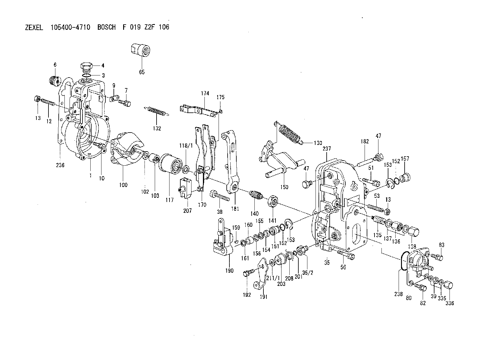
| 1. | [1] | 154000-6300 | GOVERNOR HOUSING |
| 3. | [1] | 029632-5070 | O-RING |
| 4. | [1] | 154007-2900 | CAPSULE |
| 6. | [1] | 154007-0200 | ADAPTOR |
| 7. | [1] | 020018-1840 | BLEEDER SCREW M8P1.25L18 |
| 9. | [1] | 154350-1900 | PLATE |
| 10. | [6] | 029010-6810 | BLEEDER SCREW |
| 12. | [1] | 154010-0100 | FLAT-HEAD SCREW |
| 13. | [2] | 154011-0100 | HEXAGON NUT |
| 13. | [2] | 154011-0100 | HEXAGON NUT |
| 35. | [1] | 154500-1020 | GOVERNOR COVER |
| 35/2. | [1] | 154321-0400 | BUSHING |
| 38. | [1] | 154031-2400 | FLAT-HEAD SCREW |
| 39. | [1] | 139206-0600 | UNION NUT |
| 47. | [2] | 154036-0300 | CAPSULE |
| 47. | [2] | 154036-0300 | CAPSULE |
| 51. | [2] | 020106-5040 | BLEEDER SCREW |
| 53. | [1] | 154010-0100 | FLAT-HEAD SCREW |
| 56. | [4] | 020106-3840 | BLEEDER SCREW |
| 65. | [1] | 155404-5300 | CAP |
| 80. | [1] | 154063-6820 | COVER |
| 82. | [2] | 029020-6210 | BLEEDER SCREW |
| 83. | [2] | 020006-1640 | BLEEDER SCREW M6P1L16 4T |
| 100. | [1] | 154100-9720 | FLYWEIGHT ASSEMBLY |
| 102. | [1] | 029321-2020 | LOCKING WASHER |
| 103. | [1] | 029231-2030 | UNION NUT |
| 117. | [1] | 154123-0120 | SLIDING PIECE |
| 118/1. | [0] | 029311-0010 | SHIM D14&10.1T0.2 |
| 118/1. | [0] | 029311-0180 | SHIM D14&10.1T0.3 |
| 118/1. | [0] | 029311-0190 | SHIM D14&10.1T0.40 |
| 118/1. | [0] | 029311-0210 | SHIM D14&10.1T1 |
| 118/1. | [0] | 139410-0000 | SHIM D14.0&10.1T0.5 |
| 118/1. | [0] | 139410-0100 | SHIM D14.0&10.1T1.5 |
| 118/1. | [0] | 139410-3000 | SHIM D14&10.1T2.0 |
| 118/1. | [0] | 139410-3100 | SHIM D14&10.1T3.0 |
| 118/1. | [0] | 139410-3200 | SHIM D14&10.1T4.0 |
| 130. | [1] | 154150-2700 | GOVERNOR SPRING |
| 132. | [1] | 154154-1200 | COILED SPRING |
| 135. | [1] | 154158-1320 | HEADLESS SCREW |
| 136. | [1] | 154011-1700 | UNION NUT |
| 137. | [2] | 026512-1540 | GASKET D15.4&12.2T1.50 |
| 138. | [1] | 154159-1200 | CAP NUT |
| 140. | [1] | 154177-0120 | HEADLESS SCREW |
| 141. | [1] | 029201-6010 | UNION NUT |
| 150. | [1] | 154200-7120 | SWIVELLING LEVER |
| 151. | [1] | 154204-4300 | BUSHING |
| 152. | [2] | 029631-8020 | O-RING |
| 152. | [2] | 029631-8020 | O-RING |
| 153. | [2] | 016010-1640 | LOCKING WASHER |
| 153. | [2] | 016010-1640 | LOCKING WASHER |
| 154. | [1] | 139611-0000 | PACKING RING |
| 155. | [1] | 139411-0000 | SHIM |
| 156. | [0] | 029311-1070 | SHIM D16&11T0.5 |
| 157. | [1] | 154204-4400 | BUSHING |
| 159. | [1] | 025803-1310 | WOODRUFF KEY |
| 160. | [1] | 154206-2800 | BUSHING |
| 161. | [0] | 154206-0200 | PLAIN WASHER D19.5&11.2T1.0 |
| 170. | [1] | 154210-0920 | FORK LEVER |
| 174. | [1] | 154230-3920 | STRAP |
| 175. | [1] | 016010-0540 | LOCKING WASHER |
| 181. | [1] | 154236-1500 | TENSIONING LEVER |
| 182. | [1] | 154237-0100 | BEARING PIN |
| 190. | [1] | 154341-9520 | CONTROL LEVER |
| 191. | [1] | 154304-5800 | CONTROL LEVER |
| 192. | [1] | 020006-1640 | BLEEDER SCREW M6P1L16 4T |
| 201. | [1] | 029631-0030 | O-RING &9.8W2.3 |
| 203. | [1] | 154322-0100 | CAP |
| 207. | [1] | 154326-5020 | CONTROL LEVER |
| 208. | [1] | 154327-7600 | COILED SPRING |
| 211/1. | [0] | 029311-0520 | SHIM D20.8&10.3T0.2 |
| 211/1. | [0] | 029311-0530 | SHIM D20.8&10.3T0.25 |
| 211/1. | [0] | 029311-0540 | SHIM D20.8&10.3T0.3 |
| 211/1. | [0] | 029311-0550 | SHIM D20.8&10.3T0.35 |
| 211/1. | [0] | 029311-0560 | SHIM D20.8&10.3T0.4 |
| 211/1. | [0] | 029311-0570 | SHIM D20.8&10.3T0.5 |
| 236. | [1] | 154390-0000 | GASKET |
| 237. | [1] | 154390-0300 | GASKET |
| 238. | [1] | 029635-2020 | O-RING |
| 335. | [2] | 026506-1040 | GASKET D9.9&6.2T1 |
| 336. | [1] | 154035-1600 | CAP NUT |
Include in #1:
101492-3601
as GOVERNOR
Cross reference number
Zexel num
Bosch num
Firm num
Name
105400-4710
F 019 Z2F 106
GOVERNOR
* K
* K
Information:
start by:a) remove flywheel housingb) remove valve liftersc) remove pistonsd) remove timing gear cover and oil pump1. Fasten a hoist and put the engine in position on tool (A).2. Turn the crankshaft until the timing mark on the crankshaft gear is in alignment with the timing mark on the camshaft gear. For more detail about removal of main bearings see REMOVE AND INSTALL CRANKSHAFT MAIN BEARINGS. 3. Remove bolts (1) and main bearing caps (2). Remove the lower halves of the main bearings from the caps.4. Install two of the bolts that hold the flywheel in place in the end of crankshaft. 5. Fasten a hoist and remove crankshaft (3) from the engine. The weight of the crankshaft is 54 kg (120 lb.).
Be careful not to cause damage to the crankshaft journals when the crankshaft is removed.
6. Remove the upper halves of the main bearings from the cylinder block.7. Install tooling (B) and remove the gear from the crankshaft. Install Crankshaft And Gear
1. Install the key for the crankshaft gear so it is even with the end of the crankshaft.2. Heat the crankshaft gear to a maximum temperature of 260°C (500°F). Install the gear on the crankshaft with the timing mark on the gear toward the pulley end of the crankshaft.3. Install the thrust bearing for the No. 4 main. Install the bearings dry when the clearance checks are made. Put clean engine oil on the bearings for final assembly.4. Install the upper main bearings (the bearings with oil hole) into the engine block.5. Install two of the bolts that hold the flywheel in place in the end of the crankshaft. Fasten a hoist and put the crankshaft in position in the block. Make sure the timing mark on the crankshaft gear is in alignment with the timing mark on the camshaft gear. For more detail about installation of main bearings see REMOVE AND INSTALL CRANKSHAFT MAIN BEARINGS.
When the bearing caps are installed, make sure the number on the side of the cap is next to and respective with the number on the engine block.
When the bearing clearance is checked and the engine is in a vertical position, the crankshaft will have to be lifted up with a force equal to the weight of the crankshaft and held against the upper halves of the main bearings to get a correct measurement with Plastigage. The Plastigage will not hold the weight of the crankshaft and give a correct indication. If the engine is in a horizontal position, such as on an engine stand, it is not necessary to hold the crankshaft up. Do not turn crankshaft when Plastigage is in position to check clearance. 6. Check the bearing clearance with Plastigage. Put the lower main bearings into the caps. Put the caps in position and install the bolts. Tighten the bolts in number sequence as follows: a) Tighten bolts 1 through 10 to a torque of 40 4 N m (30 3 lb.ft.).
Do not use an impact
Have questions with 105400-4710?
Group cross 105400-4710 ZEXEL
Hino
105400-4710
F 019 Z2F 106
GOVERNOR