Information governor
BOSCH
F 019 Z4E 172
f019z4e172
ZEXEL
105400-3720
1054003720
MITSUBISHI
ME018056
me018056
Rating:
Scheme ###:
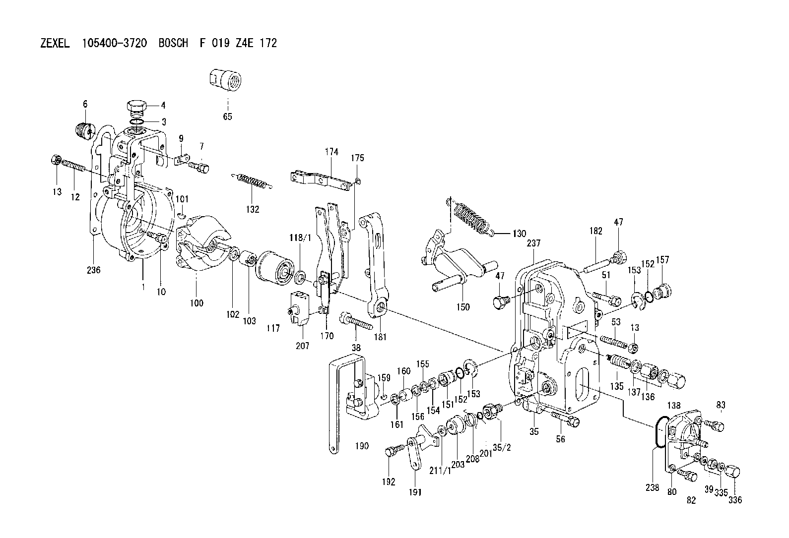
| 1. | [1] | 154000-6300 | GOVERNOR HOUSING |
| 3. | [1] | 029632-5070 | O-RING |
| 4. | [1] | 154007-2900 | CAPSULE |
| 6. | [1] | 154007-0200 | ADAPTOR |
| 7. | [1] | 020018-1840 | BLEEDER SCREW M8P1.25L18 |
| 9. | [1] | 154350-1900 | PLATE |
| 10. | [6] | 029010-6810 | BLEEDER SCREW |
| 12. | [1] | 154010-0100 | FLAT-HEAD SCREW |
| 13. | [2] | 154011-0100 | HEXAGON NUT |
| 13. | [2] | 154011-0100 | HEXAGON NUT |
| 35. | [1] | 154500-1020 | GOVERNOR COVER |
| 35/2. | [1] | 154321-0400 | BUSHING |
| 38. | [1] | 154031-2400 | FLAT-HEAD SCREW |
| 39. | [1] | 139206-0600 | UNION NUT |
| 47. | [2] | 154036-0300 | CAPSULE |
| 47. | [2] | 154036-0300 | CAPSULE |
| 51. | [2] | 020106-5040 | BLEEDER SCREW |
| 53. | [1] | 154010-0200 | FLAT-HEAD SCREW |
| 56. | [4] | 020106-3840 | BLEEDER SCREW |
| 65. | [1] | 154050-6120 | STOPPING DEVICE |
| 80. | [1] | 154063-5420 | COVER |
| 82. | [2] | 029020-6210 | BLEEDER SCREW |
| 83. | [2] | 020006-1640 | BLEEDER SCREW M6P1L16 4T |
| 100. | [1] | 154101-0120 | FLYWEIGHT |
| 101. | [1] | 025803-1610 | WOODRUFF KEY |
| 102. | [1] | 029321-2020 | LOCKING WASHER |
| 103. | [1] | 029231-2030 | UNION NUT |
| 117. | [1] | 154123-2320 | SLIDING PIECE |
| 118/1. | [0] | 029311-0010 | SHIM D14&10.1T0.2 |
| 118/1. | [0] | 029311-0180 | SHIM D14&10.1T0.3 |
| 118/1. | [0] | 029311-0190 | SHIM D14&10.1T0.40 |
| 118/1. | [0] | 029311-0210 | SHIM D14&10.1T1 |
| 118/1. | [0] | 139410-0000 | SHIM D14.0&10.1T0.5 |
| 118/1. | [0] | 139410-0100 | SHIM D14.0&10.1T1.5 |
| 118/1. | [0] | 139410-3000 | SHIM D14&10.1T2.0 |
| 118/1. | [0] | 139410-3100 | SHIM D14&10.1T3.0 |
| 118/1. | [0] | 139410-3200 | SHIM D14&10.1T4.0 |
| 130. | [1] | 154150-0100 | GOVERNOR SPRING |
| 132. | [1] | 154154-0500 | COILED SPRING |
| 135. | [1] | 154158-1020 | HEADLESS SCREW |
| 136. | [1] | 154011-1700 | UNION NUT |
| 137. | [2] | 026512-1540 | GASKET D15.4&12.2T1.50 |
| 138. | [1] | 154159-1200 | CAP NUT |
| 150. | [1] | 154200-7020 | SWIVELLING LEVER |
| 151. | [1] | 154204-4300 | BUSHING |
| 152. | [2] | 029631-8020 | O-RING |
| 152. | [2] | 029631-8020 | O-RING |
| 153. | [2] | 016010-1640 | LOCKING WASHER |
| 153. | [2] | 016010-1640 | LOCKING WASHER |
| 154. | [1] | 139611-0000 | PACKING RING |
| 155. | [1] | 139411-0000 | SHIM |
| 156. | [0] | 029311-1070 | SHIM D16&11T0.5 |
| 157. | [1] | 154204-4400 | BUSHING |
| 159. | [1] | 025803-1310 | WOODRUFF KEY |
| 160. | [1] | 154206-2800 | BUSHING |
| 161. | [0] | 154206-0200 | PLAIN WASHER D19.5&11.2T1.0 |
| 170. | [1] | 154210-0920 | FORK LEVER |
| 174. | [1] | 154230-3920 | STRAP |
| 175. | [1] | 016010-0540 | LOCKING WASHER |
| 181. | [1] | 154236-4100 | TENSIONING LEVER |
| 182. | [1] | 154237-0100 | BEARING PIN |
| 190. | [1] | 154347-2920 | CONTROL LEVER |
| 191. | [1] | 154366-3720 | CONTROL LEVER |
| 192. | [1] | 020006-3540 | BLEEDER SCREW |
| 201. | [1] | 029631-0030 | O-RING &9.8W2.3 |
| 203. | [1] | 154322-0100 | CAP |
| 207. | [1] | 154326-5020 | CONTROL LEVER |
| 208. | [1] | 154327-7700 | COILED SPRING |
| 211/1. | [0] | 029311-0520 | SHIM D20.8&10.3T0.2 |
| 211/1. | [0] | 029311-0530 | SHIM D20.8&10.3T0.25 |
| 211/1. | [0] | 029311-0540 | SHIM D20.8&10.3T0.3 |
| 211/1. | [0] | 029311-0550 | SHIM D20.8&10.3T0.35 |
| 211/1. | [0] | 029311-0560 | SHIM D20.8&10.3T0.4 |
| 211/1. | [0] | 029311-0570 | SHIM D20.8&10.3T0.5 |
| 236. | [1] | 154390-0000 | GASKET |
| 237. | [1] | 154390-0300 | GASKET |
| 238. | [1] | 029635-2020 | O-RING |
| 335. | [2] | 026506-1040 | GASKET D9.9&6.2T1 |
| 336. | [1] | 154035-1600 | CAP NUT |
Include in #1:
101492-1090
as GOVERNOR
Cross reference number
Zexel num
Bosch num
Firm num
Name
Information:
Fuel system components identified are: 1-Fuel injection nozzles. 2-Fuel lines. 3-Fuel priming pump. 4-Governor. 5-Fuel injection pump housing. 6-Fuel filter. 7-Fuel transfer pump. 8-Tachometer drive.Governor
Removal and Installation
Refer to SERVICE GUIDE for Preliminary Information.
1-Cover. 2-Plate. 3-Cover assembly.
4-Collar. 5-Housing assembly.
6-Spring. 7-Weight assembly.Governor Disassembly and Assembly
1 Guide must be damaged to be removed. When installing a new guide, form the end of the guide against and all the way around the chamfer in the governor housing.2 When assembling weights to carrier, stake four places around each dowel on both ends. Each weight must have .001-.007 in. (0,03-0,18 mm) end play and pivot freely on its dowel.Fuel Transfer Pump
Refer to SERVICE GUIDE for Preliminary Information.8S6747 Sealing Compound 1,3 Apply a thin film of 8S6747 Sealing Compound to mating surfaces when assembling. Do not allow compound to enter pump.2 Use suitable puller and step plate to remove gear. Refer to GENERAL INSTRUCTIONS. Lubricate gear teeth with multipurpose grease before assembling pump to engine.Tachometer Drive
Fuel Pump Housing
Refer to SERVICE GUIDE for Preliminary Information. 8S2315 Wrench8S2244 Extractor.1, 2, 5 Inspect seals.3 Tighten nozzle finger tight on body.4 Use 8S2315 Wrench to remove.6 Use 8S2244 Extractor to remove and install fuel pumps. When installing, sight down the pump and align the notches in the bonnet and barrel with the mark 180° from the pump gear segment center tooth. Position the pump so the notches align with the guide pins in the housing bore. Align the pump gear segment center tooth with the fuel rack center notch. Install the pump. Keep a downward force on the pump and install bushing (4) until flush with the top of the housing. If the bushing can not be assembled this far by hand, remove it. Realign the components and install again.7 When removing retaining ring, do not damage or lose the check valve or spring retained in the bonnet.8, 9 Use extreme care when inserting plunger into barrel. Barrels and plungers are matched and are not interchangeable.10 Fuel rack must be removed before removing lifters and installed after installing lifters.10, 11 Install each spacer and lifter assembly in the same location from which they were removed. Keep them together and identified as to location.12, 13 Remove bearings (12) and (13) with a suitable driver. When installing, position bearing (12) with oil passages aligned vertically (that is, one at the top and one at the bottom). Install bearing (12) .195" .005" deep from the housing face.14, 15, 16 Use commercially available camshaft bearing removal tools. Align oil hole in bearing (14) with the oil passage in the housing.Fuel Ratio Control
Fuel Priming Pump