Information governor
BOSCH
F 019 Z9E 489
f019z9e489
ZEXEL
105400-3560
1054003560

Rating:
Scheme ###:
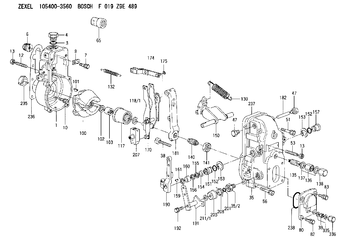
| 1. | [1] | 154000-6300 | GOVERNOR HOUSING |
| 3. | [1] | 029632-5070 | O-RING |
| 4. | [1] | 154007-2900 | CAPSULE |
| 6. | [1] | 154007-0200 | ADAPTOR |
| 7. | [1] | 020018-1840 | BLEEDER SCREW M8P1.25L18 |
| 9. | [1] | 154350-1900 | PLATE |
| 10. | [6] | 029010-6810 | BLEEDER SCREW |
| 12. | [1] | 154010-0100 | FLAT-HEAD SCREW |
| 13. | [2] | 154011-0100 | HEXAGON NUT |
| 13. | [2] | 154011-0100 | HEXAGON NUT |
| 35. | [1] | 154500-1020 | GOVERNOR COVER |
| 35/2. | [1] | 154321-0400 | BUSHING |
| 38. | [1] | 154031-2400 | FLAT-HEAD SCREW |
| 39. | [1] | 139206-0600 | UNION NUT |
| 47. | [2] | 154036-0300 | CAPSULE |
| 47. | [2] | 154036-0300 | CAPSULE |
| 51. | [2] | 020106-5040 | BLEEDER SCREW |
| 53. | [1] | 154010-0200 | FLAT-HEAD SCREW |
| 56. | [4] | 020106-3840 | BLEEDER SCREW |
| 65. | [1] | 154050-6120 | STOPPING DEVICE |
| 80. | [1] | 154063-1400 | COVER |
| 82. | [2] | 029020-6210 | BLEEDER SCREW |
| 83. | [2] | 020006-1640 | BLEEDER SCREW M6P1L16 4T |
| 100. | [1] | 154101-0520 | FLYWEIGHT |
| 101. | [1] | 025803-1610 | WOODRUFF KEY |
| 102. | [1] | 029321-2020 | LOCKING WASHER |
| 103. | [1] | 029231-2030 | UNION NUT |
| 117. | [1] | 154123-2320 | SLIDING PIECE |
| 118/1. | [0] | 029311-0010 | SHIM D14&10.1T0.2 |
| 118/1. | [0] | 029311-0180 | SHIM D14&10.1T0.3 |
| 118/1. | [0] | 029311-0190 | SHIM D14&10.1T0.40 |
| 118/1. | [0] | 029311-0210 | SHIM D14&10.1T1 |
| 118/1. | [0] | 139410-0000 | SHIM D14.0&10.1T0.5 |
| 118/1. | [0] | 139410-0100 | SHIM D14.0&10.1T1.5 |
| 118/1. | [0] | 139410-3000 | SHIM D14&10.1T2.0 |
| 118/1. | [0] | 139410-3100 | SHIM D14&10.1T3.0 |
| 118/1. | [0] | 139410-3200 | SHIM D14&10.1T4.0 |
| 130. | [1] | 154150-2700 | GOVERNOR SPRING |
| 132. | [1] | 154154-0701 | COILED SPRING |
| 135. | [1] | 154158-0920 | HEADLESS SCREW |
| 136. | [1] | 154011-1700 | UNION NUT |
| 137. | [2] | 026512-1540 | GASKET D15.4&12.2T1.50 |
| 138. | [1] | 154159-1200 | CAP NUT |
| 140. | [1] | 154185-1320 | HEADLESS SCREW |
| 141. | [1] | 029201-6010 | UNION NUT |
| 150. | [1] | 154200-7120 | SWIVELLING LEVER |
| 151. | [1] | 154204-4300 | BUSHING |
| 152. | [2] | 029631-8020 | O-RING |
| 152. | [2] | 029631-8020 | O-RING |
| 153. | [2] | 016010-1640 | LOCKING WASHER |
| 153. | [2] | 016010-1640 | LOCKING WASHER |
| 154. | [1] | 139611-0000 | PACKING RING |
| 155. | [1] | 139411-0000 | SHIM |
| 156. | [0] | 029311-1070 | SHIM D16&11T0.5 |
| 157. | [1] | 154204-4400 | BUSHING |
| 159. | [1] | 025803-1310 | WOODRUFF KEY |
| 160. | [1] | 154206-2800 | BUSHING |
| 161. | [0] | 154206-0200 | PLAIN WASHER D19.5&11.2T1.0 |
| 170. | [1] | 154210-7320 | FORK LEVER |
| 174. | [1] | 154230-3920 | STRAP |
| 175. | [1] | 016010-0540 | LOCKING WASHER |
| 181. | [1] | 154236-1500 | TENSIONING LEVER |
| 182. | [1] | 154237-0100 | BEARING PIN |
| 190. | [1] | 154309-6120 | CONTROL LEVER |
| 191. | [1] | 154365-9321 | CONTROL LEVER |
| 192. | [1] | 020006-4540 | BLEEDER SCREW M6P1L45 |
| 201. | [1] | 029631-0030 | O-RING &9.8W2.3 |
| 203. | [1] | 154322-0100 | CAP |
| 207. | [1] | 154326-5020 | CONTROL LEVER |
| 208. | [1] | 154327-7600 | COILED SPRING |
| 211/1. | [0] | 029311-0520 | SHIM D20.8&10.3T0.2 |
| 211/1. | [0] | 029311-0530 | SHIM D20.8&10.3T0.25 |
| 211/1. | [0] | 029311-0540 | SHIM D20.8&10.3T0.3 |
| 211/1. | [0] | 029311-0550 | SHIM D20.8&10.3T0.35 |
| 211/1. | [0] | 029311-0560 | SHIM D20.8&10.3T0.4 |
| 211/1. | [0] | 029311-0570 | SHIM D20.8&10.3T0.5 |
| 235. | [1] | 155412-5200 | IMPELLER WHEEL |
| 236. | [1] | 154390-0000 | GASKET |
| 237. | [1] | 154390-0300 | GASKET |
| 238. | [1] | 029635-2020 | O-RING |
| 335. | [2] | 026506-1040 | GASKET D9.9&6.2T1 |
| 336. | [1] | 154035-1600 | CAP NUT |
Include in #1:
101602-9541
as GOVERNOR
Cross reference number
Zexel num
Bosch num
Firm num
Name
105400-3560
F 019 Z9E 489
GOVERNOR
* K 14JB GOV RSV GOV
* K 14JB GOV RSV GOV
Information:
start by:a) remove pistons1. Put covers on journals of crankshaft for protection from dirt or water. 2. Remove the cylinder liners with tool (A) as shown.Install Cylinder Liners
1. Clean the cylinder liners and the liner bores in the cylinder block. 2. Install cylinder liners (1) in the block without the O-ring seals or filler band.3. Check the cylinder liner projection as follows: a) Install the 3/4"-16 NF bolts, 3 in. long and the 2F126 Washers of tooling (A) on the cylinder block next to each liner. Tighten the bolts evenly, in four steps: 10 lb.ft. (14 N m), 25 lb.ft. (35 N m) 50 lb.ft. (70 N m) and then turn to 70 lb.ft. (95 N m).b) Put the adapter plate and one plate of tooling (A) on top of the liner and install the remainder of tooling (A). Be sure the bar is in position at the center of the liner. Tighten the bolts evenly, in four steps to a torque of: 5 lb.ft. (7 N m), 15 lb.ft. (20 N m), 25 lb.ft. (35 N m), then to 50 lb.ft. (70 N m).c) Check to be sure the distance from the bottom edge of the bar to the top of the cylinder block is the same on both sides of the liner. d) Check the cylinder liner projection with tooling (B) at four locations around the liner. SPECIAL INSTRUCTION (GMG00623) is included with the tool.e) Liner projection must be .001 to .006 in. (0.03 to 0.15 mm). Measurements on the same liner must not be different by more than .002 in. (0.05 mm). Average measurements between liners next to each other must not be different by more than .002 in. (0.05 mm).The maximum difference in the average projection for all cylinder liners under one cylinder head must ot be more than .004 in. (0.10 mm). If the liner is turned in the bore it can make a difference in the liner projection.f. If the liner projection is not .001 to .006 in. (0.03 to 0.15 mm), check the thickness of the following parts: spacer plate, spacer plate gasket, and cylinder liner flange (3). The thickness of the spacer plate must be .338 .001 in. (8.59 0.03 mm). The thickness of the spacer plate gasket must be .008 .001 in. (0.20 0.03 mm). The thickness of the cylinder liner flange must be .3500 .0008 in. (8.890 0.020 mm). The cylinder liner projection can be changed by the correction of the counterbore in the block to a minimum depth of .030 in. (0.76 mm) with a cylinder block counterboring tool. See SPECIAL INSTRUCTION, Form FM055228. Shims are available for the adjustment of the liner projection. 5. Put a mark on the liner and block so the liner can be installed in the same position from which it was removed.6. Remove tooling (a) and (B). Remove the liner. Install new O-ring seals on the liners. 7. Put liquid soap on the O-ring seals
1. Clean the cylinder liners and the liner bores in the cylinder block. 2. Install cylinder liners (1) in the block without the O-ring seals or filler band.3. Check the cylinder liner projection as follows: a) Install the 3/4"-16 NF bolts, 3 in. long and the 2F126 Washers of tooling (A) on the cylinder block next to each liner. Tighten the bolts evenly, in four steps: 10 lb.ft. (14 N m), 25 lb.ft. (35 N m) 50 lb.ft. (70 N m) and then turn to 70 lb.ft. (95 N m).b) Put the adapter plate and one plate of tooling (A) on top of the liner and install the remainder of tooling (A). Be sure the bar is in position at the center of the liner. Tighten the bolts evenly, in four steps to a torque of: 5 lb.ft. (7 N m), 15 lb.ft. (20 N m), 25 lb.ft. (35 N m), then to 50 lb.ft. (70 N m).c) Check to be sure the distance from the bottom edge of the bar to the top of the cylinder block is the same on both sides of the liner. d) Check the cylinder liner projection with tooling (B) at four locations around the liner. SPECIAL INSTRUCTION (GMG00623) is included with the tool.e) Liner projection must be .001 to .006 in. (0.03 to 0.15 mm). Measurements on the same liner must not be different by more than .002 in. (0.05 mm). Average measurements between liners next to each other must not be different by more than .002 in. (0.05 mm).The maximum difference in the average projection for all cylinder liners under one cylinder head must ot be more than .004 in. (0.10 mm). If the liner is turned in the bore it can make a difference in the liner projection.f. If the liner projection is not .001 to .006 in. (0.03 to 0.15 mm), check the thickness of the following parts: spacer plate, spacer plate gasket, and cylinder liner flange (3). The thickness of the spacer plate must be .338 .001 in. (8.59 0.03 mm). The thickness of the spacer plate gasket must be .008 .001 in. (0.20 0.03 mm). The thickness of the cylinder liner flange must be .3500 .0008 in. (8.890 0.020 mm). The cylinder liner projection can be changed by the correction of the counterbore in the block to a minimum depth of .030 in. (0.76 mm) with a cylinder block counterboring tool. See SPECIAL INSTRUCTION, Form FM055228. Shims are available for the adjustment of the liner projection. 5. Put a mark on the liner and block so the liner can be installed in the same position from which it was removed.6. Remove tooling (a) and (B). Remove the liner. Install new O-ring seals on the liners. 7. Put liquid soap on the O-ring seals
Have questions with 105400-3560?
Group cross 105400-3560 ZEXEL
Nissan-Diesel
105400-3560
F 019 Z9E 489
GOVERNOR