Information governor
BOSCH
F 019 Z2F 434
f019z2f434
ZEXEL
105400-3480
1054003480
Rating:
Scheme ###:
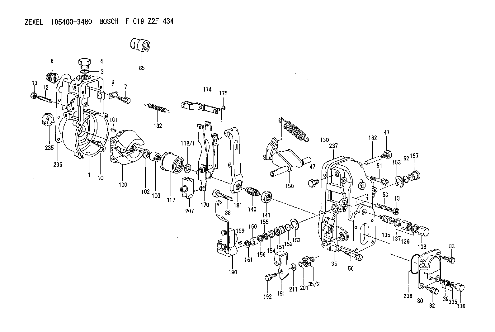
| 1. | [1] | 154000-6300 | GOVERNOR HOUSING |
| 3. | [1] | 029632-5070 | O-RING |
| 4. | [1] | 154007-2900 | CAPSULE |
| 6. | [1] | 154007-0200 | ADAPTOR |
| 7. | [1] | 020018-1840 | BLEEDER SCREW M8P1.25L18 |
| 9. | [1] | 154350-1900 | PLATE |
| 10. | [6] | 029010-6810 | BLEEDER SCREW |
| 12. | [1] | 154010-0100 | FLAT-HEAD SCREW |
| 13. | [2] | 154011-0100 | HEXAGON NUT |
| 13. | [2] | 154011-0100 | HEXAGON NUT |
| 35. | [1] | 154500-1020 | GOVERNOR COVER |
| 35/2. | [1] | 154321-0400 | BUSHING |
| 38. | [1] | 154031-2400 | FLAT-HEAD SCREW |
| 39. | [1] | 139206-0600 | UNION NUT |
| 47. | [2] | 154036-0300 | CAPSULE |
| 47. | [2] | 154036-0300 | CAPSULE |
| 51. | [2] | 020106-5040 | BLEEDER SCREW |
| 53. | [1] | 154010-1100 | FLAT-HEAD SCREW |
| 56. | [4] | 020106-3840 | BLEEDER SCREW |
| 65. | [1] | 155404-3100 | CAP |
| 80. | [1] | 154063-1400 | COVER |
| 82. | [2] | 029020-6210 | BLEEDER SCREW |
| 83. | [2] | 020006-1640 | BLEEDER SCREW M6P1L16 4T |
| 100. | [1] | 154100-9720 | FLYWEIGHT ASSEMBLY |
| 101. | [1] | 025803-1610 | WOODRUFF KEY |
| 102. | [1] | 029321-2020 | LOCKING WASHER |
| 103. | [1] | 029231-2030 | UNION NUT |
| 117. | [1] | 154123-0120 | SLIDING PIECE |
| 118/1. | [0] | 029311-0010 | SHIM D14&10.1T0.2 |
| 118/1. | [0] | 029311-0180 | SHIM D14&10.1T0.3 |
| 118/1. | [0] | 029311-0190 | SHIM D14&10.1T0.40 |
| 118/1. | [0] | 029311-0210 | SHIM D14&10.1T1 |
| 118/1. | [0] | 139410-0000 | SHIM D14.0&10.1T0.5 |
| 118/1. | [0] | 139410-0100 | SHIM D14.0&10.1T1.5 |
| 118/1. | [0] | 139410-3000 | SHIM D14&10.1T2.0 |
| 118/1. | [0] | 139410-3100 | SHIM D14&10.1T3.0 |
| 118/1. | [0] | 139410-3200 | SHIM D14&10.1T4.0 |
| 130. | [1] | 154150-2700 | GOVERNOR SPRING |
| 132. | [1] | 154154-0701 | COILED SPRING |
| 135. | [1] | 154158-0820 | HEADLESS SCREW |
| 136. | [1] | 154011-1700 | UNION NUT |
| 137. | [2] | 026512-1540 | GASKET D15.4&12.2T1.50 |
| 138. | [1] | 154159-1200 | CAP NUT |
| 140. | [1] | 154170-6820 | HEADLESS SCREW |
| 141. | [1] | 029201-6010 | UNION NUT |
| 150. | [1] | 154200-7120 | SWIVELLING LEVER |
| 151. | [1] | 154204-4300 | BUSHING |
| 152. | [2] | 029631-8020 | O-RING |
| 152. | [2] | 029631-8020 | O-RING |
| 153. | [2] | 016010-1640 | LOCKING WASHER |
| 153. | [2] | 016010-1640 | LOCKING WASHER |
| 154. | [1] | 139611-0000 | PACKING RING |
| 155. | [1] | 139411-0000 | SHIM |
| 156. | [0] | 029311-1070 | SHIM D16&11T0.5 |
| 157. | [1] | 154204-4400 | BUSHING |
| 159. | [1] | 025803-1310 | WOODRUFF KEY |
| 160. | [1] | 154206-2800 | BUSHING |
| 161. | [0] | 154206-0200 | PLAIN WASHER D19.5&11.2T1.0 |
| 170. | [1] | 154210-0920 | FORK LEVER |
| 174. | [1] | 154230-3920 | STRAP |
| 175. | [1] | 016010-0540 | LOCKING WASHER |
| 181. | [1] | 154236-1500 | TENSIONING LEVER |
| 182. | [1] | 154237-0100 | BEARING PIN |
| 190. | [1] | 154342-2920 | CONTROL LEVER |
| 191. | [1] | 154366-2400 | CONTROL LEVER |
| 192. | [1] | 020006-1640 | BLEEDER SCREW M6P1L16 4T |
| 201. | [1] | 029631-0030 | O-RING &9.8W2.3 |
| 207. | [1] | 154326-5020 | CONTROL LEVER |
| 211. | [0] | 029311-0220 | SHIM D18&10.3T0.2 |
| 211B. | [0] | 029311-0230 | SHIM D18&10.3T0.5 |
| 235. | [1] | 155412-5200 | IMPELLER WHEEL |
| 236. | [1] | 154390-0000 | GASKET |
| 237. | [1] | 154390-0300 | GASKET |
| 238. | [1] | 029635-2020 | O-RING |
| 335. | [2] | 026506-1040 | GASKET D9.9&6.2T1 |
| 336. | [1] | 154035-1600 | CAP NUT |
Include in #1:
101472-3860
as GOVERNOR
Cross reference number
Zexel num
Bosch num
Firm num
Name
105400-3480
F 019 Z2F 434
GOVERNOR
* K
* K
Information:
Remove Water Pump
start by:a) remove alternator and bracket 1. Remove two bolts that hold oil cooler bonnet (3) to the water pump.2. Remove two bolts (1) and remove elbow (2) from the water pump. Remove the gasket and O-ring seal from the elbow. 3. Remove the bolts that hold cover (4) to the water pump. Remove cover (4) from the water pump. It is not necessary to remove bolts (7). The bolts hold the cover to the timing gear cover only.4. Remove six long bolts (5) that hold the water pump to the timing cover. Remove water pump (6)Install Water Pump
1. Check the O-ring seals and gaskets and make replacements if needed. 2. Make sure O-ring seal (1) is in position on the water pump. Put water pump (2) into position in the timing gear cover. Install the bolts that hold the water pump in place. 3. Make sure the O-ring seal is in position and install cover (3) on the water pump. 4. Install the O-ring seal and gasket for elbow (4). Install elbow (4) in the water pump. Install the two bolts that hold the elbow to the water temperature regulator housing.5. Make sure the gasket is in place and install the two bolts that hold oil cooler bonnet (5) to the water pump.Disassemble Water Pump
start by:a) remove water pump 1. Remove O-ring seal (1) from the adapter.2. Remove adapter (2) from the housing. Remove the O-ring seal from the outside diameter of the adapter.3. Remove bolt (3) and retainer that hold the impeller on the shaft. 4. Use tooling (A) to remove impeller (4) from the shaft. 5. Remove spring and seal (5) from the shaft. 6. Remove four bolts (7) from retainer (6) that holds the shaft assembly to the pump housing.7. Remove O-ring seal (8) from the housing. 8. Remove gear and shaft assembly (10) from the housing.9. Remove bolt (9) and retainer from the shaft assembly. 10. Use a press to remove the shaft assembly from gear (11). Remove the retainer from the shaft assembly. 11. Remove bearing (13), spacer (14) and bearing (12) from the shaft. 12. Remove lip type seal (15) from the housing.13. Turn the housing over and remove ceramic ring (16) and the seal.Assemble Water Pump
1. Install bearing (4), spacer (3) and bearing (2) on shaft (8).2. Put retainer (1) and gear (7) in position on the shaft assembly. Install retainer (6) and bolt (5). 3. Use tooling (A) to install the lip seal in the housing. Put a small amount of SAE 30 oil on the lip of the seal. 4. Install a new O-ring seal (10) on the housing.5. Put shaft assembly (9) in position in the housing. Install the bolts that hold the retainer to the housing.
Clean water only is permitted for use as a lubricant for assistanc at installation. Do not damage or put hands on the wear sur
Have questions with 105400-3480?
Group cross 105400-3480 ZEXEL
Yanmar
Hino
Nissan-Diesel
Isuzu
105400-3480
F 019 Z2F 434
GOVERNOR