Information governor
BOSCH
F 019 Z1E 720
f019z1e720
ZEXEL
105400-3340
1054003340
Rating:
Scheme ###:
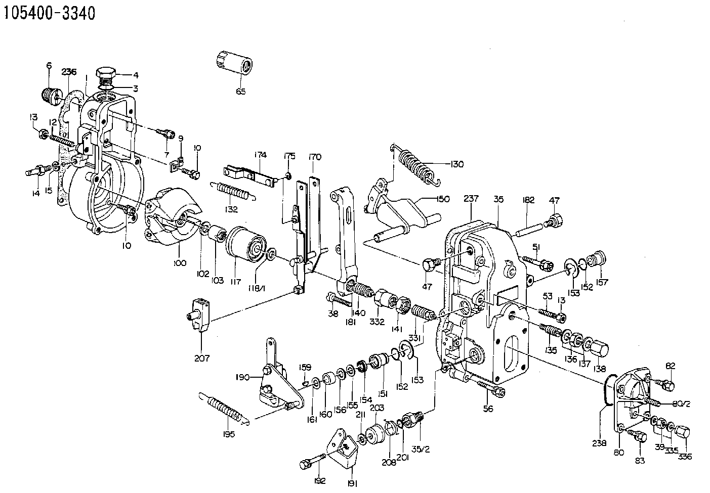
| 1. | [1] | 154000-6300 | GOVERNOR HOUSING |
| 3. | [1] | 029632-5070 | O-RING |
| 4. | [1] | 154007-2900 | CAPSULE |
| 6. | [1] | 154007-0200 | ADAPTOR |
| 7. | [1] | 020018-1840 | BLEEDER SCREW M8P1.25L18 |
| 9. | [1] | 154350-1900 | PLATE |
| 10. | [6] | 029010-6810 | BLEEDER SCREW |
| 10. | [6] | 029010-6810 | BLEEDER SCREW |
| 12. | [1] | 154010-0100 | FLAT-HEAD SCREW |
| 13. | [2] | 154011-0100 | HEXAGON NUT |
| 13. | [2] | 154011-0100 | HEXAGON NUT |
| 14. | [1] | 154012-2220 | BLEEDER SCREW |
| 15. | [1] | 014110-8440 | LOCKING WASHER |
| 35. | [1] | 154500-1020 | GOVERNOR COVER |
| 35/2. | [1] | 154321-0400 | BUSHING |
| 38. | [1] | 154031-2400 | FLAT-HEAD SCREW |
| 39. | [1] | 139206-0600 | UNION NUT |
| 47. | [2] | 154036-0300 | CAPSULE |
| 47. | [2] | 154036-0300 | CAPSULE |
| 51. | [2] | 020106-5040 | BLEEDER SCREW |
| 53. | [1] | 154010-0100 | FLAT-HEAD SCREW |
| 56. | [4] | 020106-3840 | BLEEDER SCREW |
| 65. | [1] | 155404-5300 | CAP |
| 80. | [1] | 154063-6820 | COVER |
| 82. | [2] | 029020-6210 | BLEEDER SCREW |
| 83. | [2] | 020006-1640 | BLEEDER SCREW M6P1L16 4T |
| 100. | [1] | 154101-0120 | FLYWEIGHT |
| 102. | [1] | 029321-2020 | LOCKING WASHER |
| 103. | [1] | 029231-2030 | UNION NUT |
| 117. | [1] | 154123-0120 | SLIDING PIECE |
| 118/1. | [0] | 029311-0010 | SHIM D14&10.1T0.2 |
| 118/1. | [0] | 029311-0180 | SHIM D14&10.1T0.3 |
| 118/1. | [0] | 029311-0190 | SHIM D14&10.1T0.40 |
| 118/1. | [0] | 029311-0210 | SHIM D14&10.1T1 |
| 118/1. | [0] | 139410-0000 | SHIM D14.0&10.1T0.5 |
| 118/1. | [0] | 139410-0100 | SHIM D14.0&10.1T1.5 |
| 118/1. | [0] | 139410-3000 | SHIM D14&10.1T2.0 |
| 118/1. | [0] | 139410-3100 | SHIM D14&10.1T3.0 |
| 118/1. | [0] | 139410-3200 | SHIM D14&10.1T4.0 |
| 130. | [1] | 154150-2700 | GOVERNOR SPRING |
| 132. | [1] | 154154-0701 | COILED SPRING |
| 135. | [1] | 154158-0820 | HEADLESS SCREW |
| 136. | [1] | 154011-1700 | UNION NUT |
| 137. | [2] | 026512-1540 | GASKET D15.4&12.2T1.50 |
| 138. | [1] | 154159-1200 | CAP NUT |
| 140. | [1] | 154177-0320 | HEADLESS SCREW |
| 141. | [1] | 029201-6010 | UNION NUT |
| 150. | [1] | 154200-7120 | SWIVELLING LEVER |
| 151. | [1] | 154204-4300 | BUSHING |
| 152. | [2] | 029631-8020 | O-RING |
| 152. | [2] | 029631-8020 | O-RING |
| 153. | [2] | 016010-1640 | LOCKING WASHER |
| 153. | [2] | 016010-1640 | LOCKING WASHER |
| 154. | [1] | 139611-0000 | PACKING RING |
| 155. | [1] | 139411-0000 | SHIM |
| 156. | [0] | 029311-1070 | SHIM D16&11T0.5 |
| 157. | [1] | 154204-4400 | BUSHING |
| 159. | [1] | 025803-1310 | WOODRUFF KEY |
| 160. | [1] | 154206-2800 | BUSHING |
| 161. | [0] | 154206-0200 | PLAIN WASHER D19.5&11.2T1.0 |
| 170. | [1] | 154210-0920 | FORK LEVER |
| 174. | [1] | 154230-3920 | STRAP |
| 175. | [1] | 016010-0540 | LOCKING WASHER |
| 181. | [1] | 154236-1500 | TENSIONING LEVER |
| 182. | [1] | 154237-0100 | BEARING PIN |
| 190. | [1] | 154343-1220 | CONTROL LEVER |
| 191. | [1] | 154366-1100 | CONTROL LEVER |
| 192. | [1] | 020006-1640 | BLEEDER SCREW M6P1L16 4T |
| 195. | [1] | 154314-3600 | COILED SPRING |
| 201. | [1] | 029631-0030 | O-RING &9.8W2.3 |
| 203. | [1] | 154322-0100 | CAP |
| 207. | [1] | 154326-5020 | CONTROL LEVER |
| 208. | [1] | 154327-7400 | COILED SPRING |
| 211/1. | [0] | 029311-0520 | SHIM D20.8&10.3T0.2 |
| 211/1. | [0] | 029311-0530 | SHIM D20.8&10.3T0.25 |
| 211/1. | [0] | 029311-0540 | SHIM D20.8&10.3T0.3 |
| 211/1. | [0] | 029311-0550 | SHIM D20.8&10.3T0.35 |
| 211/1. | [0] | 029311-0560 | SHIM D20.8&10.3T0.4 |
| 211/1. | [0] | 029311-0570 | SHIM D20.8&10.3T0.5 |
| 236. | [1] | 154390-0000 | GASKET |
| 237. | [1] | 154390-0300 | GASKET |
| 238. | [1] | 029635-2020 | O-RING |
| 335. | [2] | 026506-1040 | GASKET D9.9&6.2T1 |
| 336. | [1] | 154035-1600 | CAP NUT |
Include in #1:
101692-3131
as GOVERNOR
Cross reference number
Zexel num
Bosch num
Firm num
Name
Information:
start by:a) remove air compressor 1. Remove elbow (1) and adapter. Remove the gasket, screen and gasket from behind the flange.2. Remove air compressor governor (2).3. Put a mark on the head assembly and block for correct assembly. 4. Remove six bolts (3). Remove head assembly (4). 5. Remove inlet valve springs (5) from the head assembly.6. Remove discharge valve seats (6). 7. Remove discharge valves (7). Remove springs from behind the valves. Check the discharge valve stops for wear or damage. If the discharge valve travel exceeds .057 in. (1.45 mm), make a replacement of the head assembly. 8. Remove inlet valves (8) from guides. Remove guides (9) from around the inlet valve seats. 9. Remove unloader spring (10), spring seat and spring saddle (12).10. Remove unloader plungers (11) and guides. 11. To remove unloader pistons (13) from the bore, put a cover over the inlet port, then blow air pressure in the governor mounting pad unloader port (14). 12. Check inlet valve seats (15) and unloader bore bushings (16) for damage or wear. If necessary, make a replacement. 13. Remove bolts (17). Remove cover (18) and gasket from the crankcase assembly.14. Put marks on the rod bearing caps and rods for correct assembly. 15. Remove bolts (19) and locks. Remove rod bearing caps (20). Push the pistons and rods through the top of the crankcase assembly. 16. Remove rod pin (21) from the piston. Remove rod (23).17. Remove bearings (22) from the rods and caps. 18. Use tooling (A) to remove bushing (24) from the rod. 19. Remove buttons (25) from each end of the rod pins. 20. Remove piston rings (26) from piston (27) with an approved ring expander. 21. Remove O-ring seal (29) from the crankshaft.22. Remove bolts (28). Remove adapter (30) from the crankcase assembly. 23. Remove three O-ring seals (32) from the adapter.24. Remove thrust bearing (31). 25. Use tooling (A) and a press to remove the bearing from the adapter.
Do not cause damage to the bearing surfaces of the crankshaft when it is removed from the crankcase assembly.
26. Remove crankshaft (33) from the crankcase assembly. 27. Remove bolts (34). Remove cover (35). Remove two O-ring seals from the crankcase assembly. 28. Remove O-ring seal (37) from the cover.29. Remove thrust bearing (36). 30. Remove bearing (38) from the cover.Assemble Air Compressor
1. Check all parts for damage or wear. If necessary, make a replacement with a new part.2. Make sure all parts are clean and free of dirt and foreign material. 3. Use tool (A) and a press to install the bearing in cover (1). 4. Install O-ring seal (3) on the cover.5. Install thrust bearing (2). 6. Install O-ring seals (4) in the crankcase assembly.7. Put a small amount of SAE 30 oil on the O-ring seal and install the cover on crankcase assembly (5). Tighten the bolts to a torque of 25 to 35 lb.ft. (35 to 45 N m). 8. Put crankshaft (6) in position in the crankcase assembly.