Information governor
BOSCH
F 019 Z1E 565
f019z1e565
ZEXEL
105400-3250
1054003250
NISSAN-DIESEL
19109Z5564
19109z5564
Rating:
Scheme ###:
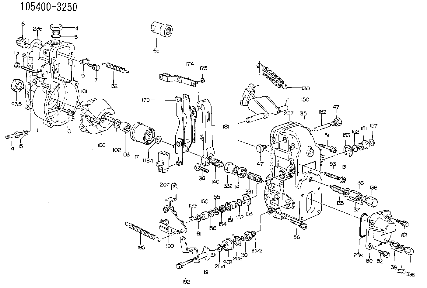
| 1. | [1] | 154000-6300 | GOVERNOR HOUSING |
| 3. | [1] | 029632-5070 | O-RING |
| 4. | [1] | 154007-2900 | CAPSULE |
| 6. | [1] | 154007-0200 | ADAPTOR |
| 7. | [1] | 020018-1840 | BLEEDER SCREW M8P1.25L18 |
| 9. | [1] | 154350-1900 | PLATE |
| 10. | [6] | 029010-6810 | BLEEDER SCREW |
| 12. | [1] | 154010-0100 | FLAT-HEAD SCREW |
| 13. | [2] | 154011-0100 | HEXAGON NUT |
| 13. | [2] | 154011-0100 | HEXAGON NUT |
| 14. | [1] | 154012-2220 | BLEEDER SCREW |
| 15. | [1] | 014110-8440 | LOCKING WASHER |
| 35. | [1] | 154500-1020 | GOVERNOR COVER |
| 35/2. | [1] | 154321-0400 | BUSHING |
| 38. | [1] | 154031-3000 | FLAT-HEAD SCREW |
| 39. | [1] | 139206-0600 | UNION NUT |
| 47. | [2] | 154036-0300 | CAPSULE |
| 47. | [2] | 154036-0300 | CAPSULE |
| 51. | [2] | 020106-5040 | BLEEDER SCREW |
| 53. | [1] | 154010-0200 | FLAT-HEAD SCREW |
| 56. | [4] | 020106-3840 | BLEEDER SCREW |
| 65. | [1] | 154050-6120 | STOPPING DEVICE |
| 80. | [1] | 154063-5100 | COVER |
| 82. | [2] | 029020-6210 | BLEEDER SCREW |
| 83. | [2] | 020006-1640 | BLEEDER SCREW M6P1L16 4T |
| 100. | [1] | 154101-0520 | FLYWEIGHT |
| 101. | [1] | 025803-1610 | WOODRUFF KEY |
| 102. | [1] | 029321-2020 | LOCKING WASHER |
| 103. | [1] | 029231-2030 | UNION NUT |
| 117. | [1] | 154123-0120 | SLIDING PIECE |
| 118/1. | [0] | 029311-0010 | SHIM D14&10.1T0.2 |
| 118/1. | [0] | 029311-0180 | SHIM D14&10.1T0.3 |
| 118/1. | [0] | 029311-0190 | SHIM D14&10.1T0.40 |
| 118/1. | [0] | 029311-0210 | SHIM D14&10.1T1 |
| 118/1. | [0] | 139410-0000 | SHIM D14.0&10.1T0.5 |
| 118/1. | [0] | 139410-0100 | SHIM D14.0&10.1T1.5 |
| 118/1. | [0] | 139410-3000 | SHIM D14&10.1T2.0 |
| 118/1. | [0] | 139410-3100 | SHIM D14&10.1T3.0 |
| 118/1. | [0] | 139410-3200 | SHIM D14&10.1T4.0 |
| 130. | [1] | 154150-2700 | GOVERNOR SPRING |
| 132. | [1] | 154154-0701 | COILED SPRING |
| 135. | [1] | 154158-0920 | HEADLESS SCREW |
| 136. | [1] | 154011-1700 | UNION NUT |
| 137. | [2] | 026512-1540 | GASKET D15.4&12.2T1.50 |
| 138. | [1] | 154159-1200 | CAP NUT |
| 140. | [1] | 154185-1320 | HEADLESS SCREW |
| 141. | [1] | 029201-6080 | UNION NUT |
| 150. | [1] | 154200-7120 | SWIVELLING LEVER |
| 151. | [1] | 154204-4300 | BUSHING |
| 151. | [1] | 154204-4300 | BUSHING |
| 152. | [2] | 029631-8020 | O-RING |
| 152. | [2] | 029631-8020 | O-RING |
| 153. | [2] | 016010-1640 | LOCKING WASHER |
| 153. | [2] | 016010-1640 | LOCKING WASHER |
| 154. | [1] | 139611-0000 | PACKING RING |
| 155. | [1] | 139411-0000 | SHIM |
| 156. | [0] | 029311-1070 | SHIM D16&11T0.5 |
| 157. | [1] | 154204-4400 | BUSHING |
| 159. | [1] | 025803-1310 | WOODRUFF KEY |
| 160. | [1] | 154206-2800 | BUSHING |
| 161. | [0] | 154206-0200 | PLAIN WASHER D19.5&11.2T1.0 |
| 170. | [1] | 154210-7320 | FORK LEVER |
| 174. | [1] | 154230-3920 | STRAP |
| 175. | [1] | 016010-0540 | LOCKING WASHER |
| 181. | [1] | 154236-1500 | TENSIONING LEVER |
| 182. | [1] | 154237-0100 | BEARING PIN |
| 190. | [1] | 154343-0820 | CONTROL LEVER |
| 191. | [1] | 154366-2120 | CONTROL LEVER |
| 192. | [1] | 020006-4540 | BLEEDER SCREW M6P1L45 |
| 195. | [1] | 154314-2600 | COILED SPRING |
| 201. | [1] | 029631-0030 | O-RING &9.8W2.3 |
| 203. | [1] | 154322-0100 | CAP |
| 207. | [1] | 154326-5020 | CONTROL LEVER |
| 208. | [1] | 154327-7600 | COILED SPRING |
| 211/1. | [0] | 029311-0520 | SHIM D20.8&10.3T0.2 |
| 211/1. | [0] | 029311-0530 | SHIM D20.8&10.3T0.25 |
| 211/1. | [0] | 029311-0540 | SHIM D20.8&10.3T0.3 |
| 211/1. | [0] | 029311-0550 | SHIM D20.8&10.3T0.35 |
| 211/1. | [0] | 029311-0560 | SHIM D20.8&10.3T0.4 |
| 211/1. | [0] | 029311-0570 | SHIM D20.8&10.3T0.5 |
| 235. | [1] | 155412-5200 | IMPELLER WHEEL |
| 236. | [1] | 154390-0000 | GASKET |
| 237. | [1] | 154390-0300 | GASKET |
| 238. | [1] | 029635-2020 | O-RING |
| 331. | [1] | 154172-6820 | HEADLESS SCREW |
| 332. | [1] | 029201-6010 | UNION NUT |
| 335. | [2] | 026506-1040 | GASKET D9.9&6.2T1 |
| 336. | [1] | 154035-1600 | CAP NUT |
Include in #1:
101602-9581
as GOVERNOR
Cross reference number
Zexel num
Bosch num
Firm num
Name
Information:
High Fuel Consumption (Diagnosis with Chassis Dynamometer) (Diagnosis with Chassis Dynamometer)1. Preparation of vehicle for fuel consumption test (consult dynamometer manufacturer's operating instructions for specific details on correct operation). Always perform the Primary Engine Test procedure before vehicle is installed on chassis dynamometer.a. Place vehicle on the chassis dynamometer. Tie the vehicle in a way that will not add any load to the drive wheels. Do not pull wheels down into dynamometer drive rolls.Check the radiator coolant level, crankcase oil level, tire pressure, tire condition, remove rocks from the tire tread and connect exhaust system.
Recapped tires should be run on a chassis dynamometer only at the customer's own risk.
b. The maximum acceptable fuel rate must be calculated for the customer's engine by use of the formula that follows: Find the rated brake specific fuel consumption (lb-bhp/hr) from the RACK SETTING INFORMATION and add .010 manufacturing tolerance. Multiply this value by the advertised engine horsepower (plus 3% manf. tol.) and divide by the density of the fuel (lbs/gal).c. Calculate the allowable limits that the customer can expect from his engine and present these figures to him. Caterpillar engines are rated with the conditions that follow: Measure and record these variables. Advertised engine bhp (less 3% manufacturing tolerance) can then be corrected to test conditions by use of procedure and correction tables found in Special Instruction GEG01024.2. Operate vehicle at 60% of rated speed with moderate load until oil and coolant temperatures reach their normal range for operation.
If there is a heavy vibration, drive shaft whip, tire bounce, etc., do not continue with dynamometer test until cause of the problem is corrected. Engines that have had new internal parts installed should be operated on a run-in schedule before operation at full load.
Put transmission in direct gear and the differential in the highest speed ratio. Operate vehicle at maximum engine speed and increase chassis dynamometer load until a speed of 50 rpm less than rated speed is reached (continuity light should be on). Maintain this speed for one minute and record the engine speed, wheel horsepower and fuel rate.3. If the fuel rate and the wheel horsepower are both acceptable, then the engine is not the cause of the complaint, or the complaint is not valid. Refer to section PROBLEM WITH VEHICLE OR VEHICLE OPERATION.4. If the wheel horsepower is low, regardless of how the fuel rate measures, refer to the LOW POWER TROUBLESHOOTING CHART. The low power problem must be corrected first.5. If fuel rate and wheel horsepower are both too high, check the balance point of the engine (speed at which the rack adjustment screw just touches the torque spring or stop bar). At this point the continuity light should flicker (go off and on dimly).If the balance point is high, the high idle will have to be decreased to lower the balance point to the correct rpm (point at which the continuity light just comes on). If the balance point is correct, see Procedure No. 8.6. If the