Information governor
BOSCH
F 019 Z1E 715
f019z1e715
ZEXEL
105400-3060
1054003060
Rating:
Scheme ###:
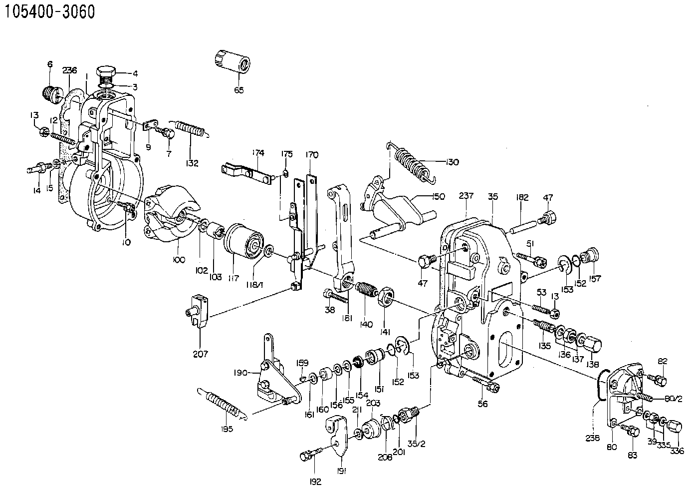
| 1. | [1] | 154000-6300 | GOVERNOR HOUSING |
| 3. | [1] | 029632-5070 | O-RING |
| 4. | [1] | 154007-2900 | CAPSULE |
| 6. | [1] | 154007-0200 | ADAPTOR |
| 7. | [1] | 020018-1840 | BLEEDER SCREW M8P1.25L18 |
| 9. | [1] | 154350-1900 | PLATE |
| 10. | [6] | 029010-6810 | BLEEDER SCREW |
| 12. | [1] | 154010-0100 | FLAT-HEAD SCREW |
| 13. | [2] | 154011-0100 | HEXAGON NUT |
| 13. | [2] | 154011-0100 | HEXAGON NUT |
| 14. | [1] | 154012-2220 | BLEEDER SCREW |
| 15. | [1] | 014110-8440 | LOCKING WASHER |
| 35. | [1] | 154500-1020 | GOVERNOR COVER |
| 35/2. | [1] | 154321-0400 | BUSHING |
| 38. | [1] | 154031-2400 | FLAT-HEAD SCREW |
| 39. | [1] | 139206-0600 | UNION NUT |
| 47. | [2] | 154036-0300 | CAPSULE |
| 47. | [2] | 154036-0300 | CAPSULE |
| 51. | [2] | 020106-5040 | BLEEDER SCREW |
| 53. | [1] | 154010-0100 | FLAT-HEAD SCREW |
| 56. | [4] | 020106-3840 | BLEEDER SCREW |
| 65. | [1] | 155404-6200 | CAP |
| 80. | [1] | 154063-6820 | COVER |
| 80. | [1] | 154063-6820 | COVER |
| 82. | [2] | 029020-6210 | BLEEDER SCREW |
| 83. | [2] | 020006-1640 | BLEEDER SCREW M6P1L16 4T |
| 100. | [1] | 154101-0020 | FLYWEIGHT ASSEMBLY |
| 102. | [1] | 029321-2020 | LOCKING WASHER |
| 103. | [1] | 029231-2030 | UNION NUT |
| 117. | [1] | 154123-0120 | SLIDING PIECE |
| 118/1. | [0] | 029311-0010 | SHIM D14&10.1T0.2 |
| 118/1. | [0] | 029311-0180 | SHIM D14&10.1T0.3 |
| 118/1. | [0] | 029311-0190 | SHIM D14&10.1T0.40 |
| 118/1. | [0] | 029311-0210 | SHIM D14&10.1T1 |
| 118/1. | [0] | 139410-0000 | SHIM D14.0&10.1T0.5 |
| 118/1. | [0] | 139410-0100 | SHIM D14.0&10.1T1.5 |
| 118/1. | [0] | 139410-3000 | SHIM D14&10.1T2.0 |
| 118/1. | [0] | 139410-3100 | SHIM D14&10.1T3.0 |
| 118/1. | [0] | 139410-3200 | SHIM D14&10.1T4.0 |
| 130. | [1] | 154150-0400 | GOVERNOR SPRING |
| 132. | [1] | 154154-0701 | COILED SPRING |
| 135. | [1] | 154158-1320 | HEADLESS SCREW |
| 136. | [1] | 154011-1700 | UNION NUT |
| 137. | [2] | 026512-1540 | GASKET D15.4&12.2T1.50 |
| 138. | [1] | 154159-1200 | CAP NUT |
| 140. | [1] | 154177-0420 | HEADLESS SCREW |
| 141. | [1] | 029201-6010 | UNION NUT |
| 150. | [1] | 154200-7020 | SWIVELLING LEVER |
| 151. | [1] | 154204-4300 | BUSHING |
| 152. | [2] | 029631-8020 | O-RING |
| 152. | [2] | 029631-8020 | O-RING |
| 153. | [2] | 016010-1640 | LOCKING WASHER |
| 153. | [2] | 016010-1640 | LOCKING WASHER |
| 154. | [1] | 139611-0000 | PACKING RING |
| 155. | [1] | 139411-0000 | SHIM |
| 156. | [0] | 029311-1070 | SHIM D16&11T0.5 |
| 157. | [1] | 154204-4400 | BUSHING |
| 159. | [1] | 025803-1310 | WOODRUFF KEY |
| 160. | [1] | 154206-2800 | BUSHING |
| 161. | [0] | 154206-0200 | PLAIN WASHER D19.5&11.2T1.0 |
| 170. | [1] | 154210-7320 | FORK LEVER |
| 174. | [1] | 154230-3920 | STRAP |
| 175. | [1] | 016010-0540 | LOCKING WASHER |
| 181. | [1] | 154236-4100 | TENSIONING LEVER |
| 182. | [1] | 154237-0100 | BEARING PIN |
| 190. | [1] | 154341-9620 | CONTROL LEVER |
| 191. | [1] | 154304-5800 | CONTROL LEVER |
| 192. | [1] | 020006-1640 | BLEEDER SCREW M6P1L16 4T |
| 195. | [1] | 154314-2500 | COILED SPRING |
| 201. | [1] | 029631-0030 | O-RING &9.8W2.3 |
| 203. | [1] | 154322-0100 | CAP |
| 207. | [1] | 154326-5020 | CONTROL LEVER |
| 208. | [1] | 154327-7600 | COILED SPRING |
| 211/1. | [0] | 029311-0520 | SHIM D20.8&10.3T0.2 |
| 211/1. | [0] | 029311-0530 | SHIM D20.8&10.3T0.25 |
| 211/1. | [0] | 029311-0540 | SHIM D20.8&10.3T0.3 |
| 211/1. | [0] | 029311-0550 | SHIM D20.8&10.3T0.35 |
| 211/1. | [0] | 029311-0560 | SHIM D20.8&10.3T0.4 |
| 211/1. | [0] | 029311-0570 | SHIM D20.8&10.3T0.5 |
| 236. | [1] | 154390-0000 | GASKET |
| 237. | [1] | 154390-0300 | GASKET |
| 238. | [1] | 029635-2020 | O-RING |
| 335. | [2] | 026506-1040 | GASKET D9.9&6.2T1 |
| 336. | [1] | 154035-1600 | CAP NUT |
Include in #1:
101692-3041
as GOVERNOR
Cross reference number
Zexel num
Bosch num
Firm num
Name
105400-3060
F 019 Z1E 715
GOVERNOR
* K
* K
Information:
2. Remove nuts (1) from studs for main bearing caps (2).3. Remove the main bearing caps.4. Install rubber hose over each of the two studs at both ends of the block. This will protect the crankshaft during removal and installation. 5. Remove the crankshaft from the cylinder block. Weight of crankshaft is 300 lb. (136 kg).6. Remove the main bearings from cylinder block and main bearing caps.
If main bearings are not replaced, old bearings must be installed in same location from which they were removed.
Install Crankshaft
1. Put timing marks (1) on all timing gears in alignment.2. Clean surfaces for bearings in cylinder block. Install upper halves of bearings in block. Put clean oil on bearings.
If replacement of the bearings is not made, old bearings must be installed in same location from which they were removed.
3. Clean bearing caps, and install lower halves of bearings in caps. 4. Fasten a hoist to crankshaft and put it into place in the block with "V" mark on crankshaft gear in alignment with "V" mark on cluster gear. 5. Check bearing clearance with wire (A). Install bearing caps, and tighten both nuts to 75 5 lb. ft. (101.7 6.8 N m). Put a mark across the nuts and studs, and turn nuts an additional 120° from mark. Remove caps and check thickness of wire (A) to find bearing clearance. Bearing clearance must be .0035 to .0066 in. (0.089 to 0.168 mm) for new parts. Maximum permissible clearance for used parts is .010 in. (0.25 mm).6. Put clean oil on threads of studs, face of nuts, and lower halves of bearings. Put bearing caps in their respective positions with number on cap same as number on block, and groove in bearing cap on same side as groove in cylinder block. Install nuts and tighten to 75 5 lb.ft. (101.7 6.8 N m). Put a mark across the nuts and studs, and turn nuts an additional 120° from mark. 7. Use indicator group (B) to check the crankshaft end plate as controlled by lower bearing of No. 7 bearing cap. End play with new parts should be .006 to .018 in. (0.15 to 0.46 mm). Maximum permissible end play with used parts is .035 in. (0.89 mm).end by: a) install flywheel housingb) install front coverc) install pistonsd) install engine and torque divider
Have questions with 105400-3060?
Group cross 105400-3060 ZEXEL
Hino
105400-3060
F 019 Z1E 715
GOVERNOR