Information governor
BOSCH
9 420 612 734
9420612734
ZEXEL
105400-2950
1054002950
YANMAR
12741661550
12741661550

Rating:
Scheme ###:
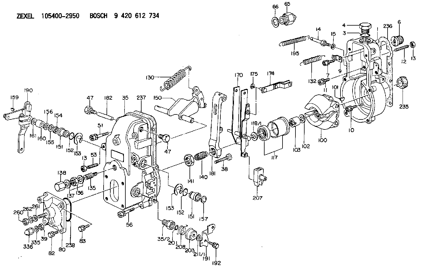
| 1. | [1] | 154000-6300 | GOVERNOR HOUSING |
| 3. | [1] | 029632-5070 | O-RING |
| 4. | [1] | 154007-2900 | CAPSULE |
| 6. | [1] | 154007-0200 | ADAPTOR |
| 7. | [1] | 020018-1840 | BLEEDER SCREW M8P1.25L18 |
| 9. | [1] | 154350-1800 | PLATE |
| 10. | [5] | 029010-6810 | BLEEDER SCREW |
| 11. | [1] | 020006-1640 | BLEEDER SCREW M6P1L16 4T |
| 12. | [1] | 154010-0100 | FLAT-HEAD SCREW |
| 13. | [2] | 154011-0100 | HEXAGON NUT |
| 13. | [2] | 154011-0100 | HEXAGON NUT |
| 14. | [1] | 154012-1720 | BLEEDER SCREW |
| 15. | [1] | 014110-8440 | LOCKING WASHER |
| 35. | [1] | 154500-3020 | GOVERNOR COVER |
| 35/2. | [1] | 154321-0400 | BUSHING |
| 38. | [1] | 154031-2400 | FLAT-HEAD SCREW |
| 39. | [1] | 139206-0600 | UNION NUT |
| 47. | [2] | 154036-0300 | CAPSULE |
| 47. | [2] | 154036-0300 | CAPSULE |
| 51. | [2] | 020106-5040 | BLEEDER SCREW |
| 53. | [1] | 154010-0300 | FLAT-HEAD SCREW |
| 56. | [4] | 020106-3840 | BLEEDER SCREW |
| 65. | [1] | 153020-4420 | STOPPING DEVICE |
| 66. | [1] | 026518-2240 | GASKET D21.9&18.2T1 |
| 80. | [1] | 154063-4520 | COVER |
| 82. | [2] | 029020-6210 | BLEEDER SCREW |
| 83. | [2] | 020006-1640 | BLEEDER SCREW M6P1L16 4T |
| 100. | [1] | 154101-0020 | FLYWEIGHT ASSEMBLY |
| 101. | [1] | 025803-1610 | WOODRUFF KEY |
| 102. | [1] | 029321-2020 | LOCKING WASHER |
| 103. | [1] | 029231-2030 | UNION NUT |
| 117. | [1] | 154123-0120 | SLIDING PIECE |
| 118/1. | [0] | 029311-0010 | SHIM D14&10.1T0.2 |
| 118/1. | [0] | 029311-0180 | SHIM D14&10.1T0.3 |
| 118/1. | [0] | 029311-0190 | SHIM D14&10.1T0.40 |
| 118/1. | [0] | 029311-0210 | SHIM D14&10.1T1 |
| 118/1. | [0] | 139410-0000 | SHIM D14.0&10.1T0.5 |
| 118/1. | [0] | 139410-0100 | SHIM D14.0&10.1T1.5 |
| 118/1. | [0] | 139410-3000 | SHIM D14&10.1T2.0 |
| 118/1. | [0] | 139410-3100 | SHIM D14&10.1T3.0 |
| 118/1. | [0] | 139410-3200 | SHIM D14&10.1T4.0 |
| 130. | [1] | 154150-2700 | GOVERNOR SPRING |
| 132. | [1] | 154154-0701 | COILED SPRING |
| 135. | [1] | 154157-1620 | HEADLESS SCREW |
| 136. | [1] | 029201-2130 | UNION NUT M12P1.0H6 |
| 137. | [2] | 026512-1540 | GASKET D15.4&12.2T1.50 |
| 138. | [1] | 154159-1200 | CAP NUT |
| 140. | [1] | 154185-1320 | HEADLESS SCREW |
| 141. | [1] | 029201-6010 | UNION NUT |
| 150. | [1] | 154200-7120 | SWIVELLING LEVER |
| 151. | [1] | 154204-3000 | BUSHING |
| 151. | [1] | 154204-3000 | BUSHING |
| 152. | [2] | 029631-8020 | O-RING |
| 152. | [2] | 029631-8020 | O-RING |
| 153. | [2] | 016010-1640 | LOCKING WASHER |
| 153. | [2] | 016010-1640 | LOCKING WASHER |
| 154. | [1] | 139611-0000 | PACKING RING |
| 155. | [1] | 139411-0000 | SHIM |
| 156. | [0] | 029311-1070 | SHIM D16&11T0.5 |
| 157. | [1] | 154204-3100 | BUSHING |
| 159. | [1] | 025803-1310 | WOODRUFF KEY |
| 160. | [1] | 154206-2800 | BUSHING |
| 161. | [0] | 154206-0200 | PLAIN WASHER D19.5&11.2T1.0 |
| 170. | [1] | 154211-4320 | FORK LEVER |
| 174. | [1] | 154230-3920 | STRAP |
| 175. | [1] | 016010-0540 | LOCKING WASHER |
| 181. | [1] | 154236-1500 | TENSIONING LEVER |
| 182. | [1] | 154237-0100 | BEARING PIN |
| 190. | [1] | 154345-5320 | CONTROL LEVER |
| 191. | [1] | 154304-2800 | CONTROL LEVER |
| 192. | [1] | 020006-1640 | BLEEDER SCREW M6P1L16 4T |
| 195. | [1] | 154314-2600 | COILED SPRING |
| 201. | [1] | 029631-0030 | O-RING &9.8W2.3 |
| 203. | [1] | 154322-0100 | CAP |
| 207. | [1] | 154326-5120 | CONTROL LEVER |
| 208. | [1] | 154327-7300 | COILED SPRING |
| 211/1. | [0] | 029311-0520 | SHIM D20.8&10.3T0.2 |
| 211/1. | [0] | 029311-0530 | SHIM D20.8&10.3T0.25 |
| 211/1. | [0] | 029311-0540 | SHIM D20.8&10.3T0.3 |
| 211/1. | [0] | 029311-0550 | SHIM D20.8&10.3T0.35 |
| 211/1. | [0] | 029311-0560 | SHIM D20.8&10.3T0.4 |
| 211/1. | [0] | 029311-0570 | SHIM D20.8&10.3T0.5 |
| 235. | [1] | 155412-5200 | IMPELLER WHEEL |
| 236. | [1] | 154390-0000 | GASKET |
| 237. | [1] | 154390-0300 | GASKET |
| 238. | [1] | 029635-2020 | O-RING |
| 260. | [1] | 013020-8040 | UNION NUT M8P1.25H7 |
| 261. | [1] | 014010-8140 | PLAIN WASHER D18&8.5T1.6 |
| 262. | [1] | 014110-8440 | LOCKING WASHER |
| 335. | [2] | 026506-1040 | GASKET D9.9&6.2T1 |
| 336. | [1] | 154035-1600 | CAP NUT |
Cross reference number
Zexel num
Bosch num
Firm num
Name
Information:
1. Loosen the clamps on hose (3), remove nuts (2) and remove temperature regulator housing (1) and the gasket from the cylinder head. 2. Remove bolt (5) and the nut from the bracket.3. Remove bolts (6) and (7) that hold the fuel injection lines in position. Remove fuel injection lines (4) from the engine.
Put protection caps (5F2807) and plugs (2F2990) on the injection lines and pumps to keep dirt and foreign material out of the fuel system.
4. Disconnect air lines (8) and (9) from the cylinder head. 5. Remove two locks and bolts (10). Remove the dowel used for location of the rear of the camshafts and remove four bolts (12). Remove valve cover base (11) and the gasket from the cylinder head. 6. Remove bolts (14) that hold cylinder head (13) to the cylinder block. 7. Install four 3/8"-16 NC forged eyebolts in the cylinder head as shown. Fasten a hoist and remove the cylinder head. The weight of the cylinder head is 450 lb. (203 kg).8. Remove the water seals and the head gasket from the spacer plate. 9. Remove the O-ring seal from dowel (16).10. Install six 3/8"-16 NC forcing screws in spacer plate (15). Tighten the screws evenly until the spacer plate is free of the dowels. Remove spacer plate (15).11. Remove the second O-ring seal from dowel (16).Install Cylinder Head And Spacer Plate
A new spacer plate gasket must be installed when the cylinder head is removed.1. Thoroughly clean the top surface of the cylinder block, both surfaces of the spacer plate and the bottom surface of the cylinder head. 2. Put the O-ring seal in position around dowel (1).3. Put a new gasket in position on the cylinder block.
Both surfaces of the spacer plate and the top of the cylinder block must be clean. Do not use a gasket adhesive on these surfaces.
4. Install spacer plate (2) on the cylinder block. 5. Install the O-ring seal on the spacer plate around dowel (1).6. Check the cylinder liner projection. See INSTALL CYLINDER LINERS.7. Put a new cylinder head gasket and water seals in position on the spacer plate. 8. Install two 3/4"-10 NC guide bolts 11 in. long in the cylinder block. Install four 3/8"-16 NC forged eyebolts in the cylinder head. Fasten a hoist and put the cylinder head in position on the guide bolts and lower it on the engine. 9. Put 9M3710 Anti-Seize Compound on the threads of cylinder head bolts (3) and the washer faces. Install bolts (3), the washers and tighten as follows: a) Tighten the bolts in number sequence shown to a torque of 200 lb. ft. (270 N m).b) Tighten the bolts in number sequence shown to a torque of 330 10 lb. ft. (447 14 N m). c) Tighten the bolts in number sequence shown (hand tighten) to a torque of 330 10 lb. ft. (447 14 N m). 10. Put the gasket and valve cover base (4) in position on the