Information governor
BOSCH
9 420 614 168
9420614168
ZEXEL
105400-2630
1054002630
Rating:
Scheme ###:
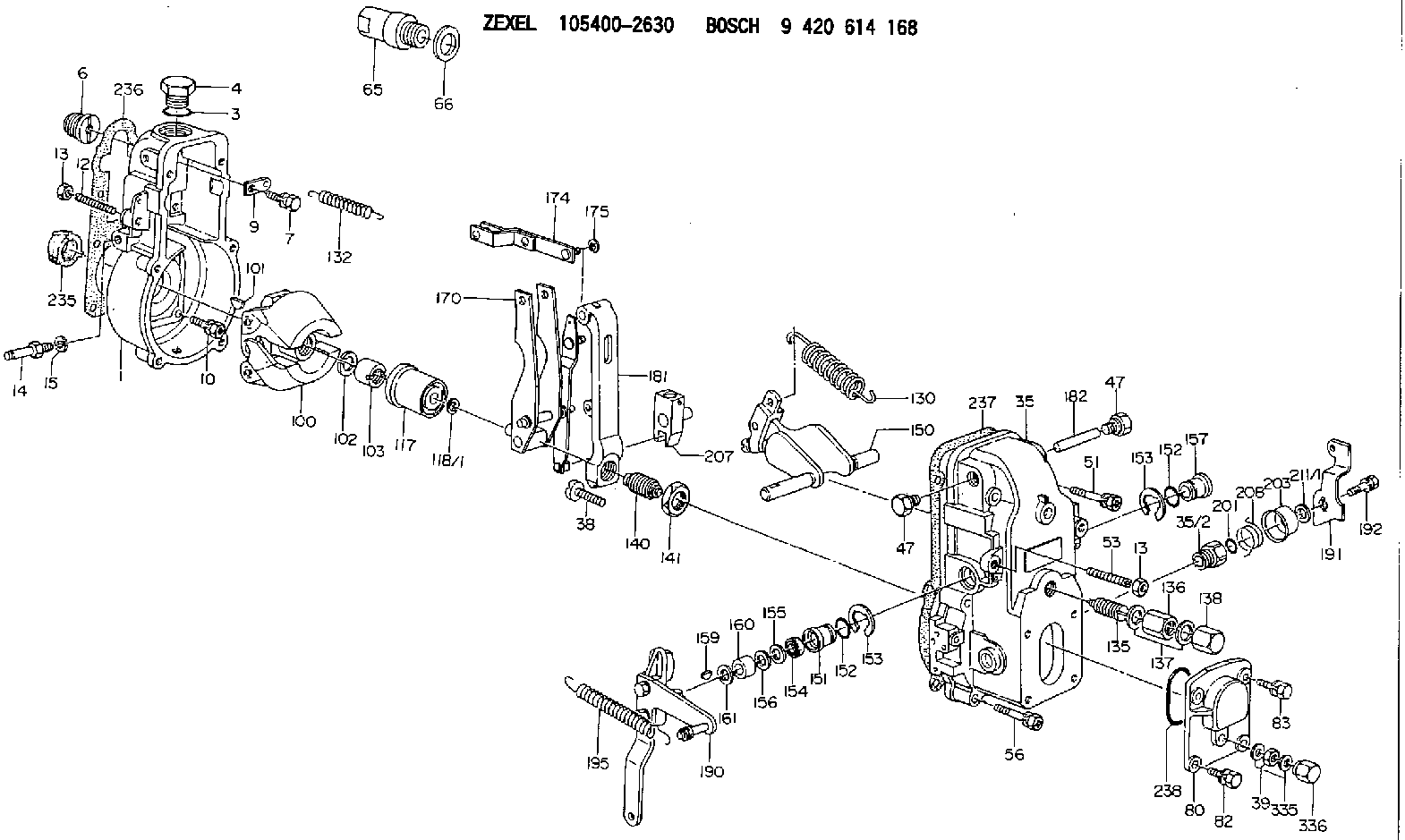
| 1. | [1] | 154000-6300 | GOVERNOR HOUSING |
| 3. | [1] | 029632-5070 | O-RING |
| 4. | [1] | 154007-2900 | CAPSULE |
| 6. | [1] | 154007-0200 | ADAPTOR |
| 7. | [1] | 020018-1840 | BLEEDER SCREW M8P1.25L18 |
| 9. | [1] | 154350-1900 | PLATE |
| 10. | [6] | 029010-6810 | BLEEDER SCREW |
| 12. | [1] | 154010-0100 | FLAT-HEAD SCREW |
| 13. | [2] | 154011-0100 | HEXAGON NUT |
| 13. | [2] | 154011-0100 | HEXAGON NUT |
| 14. | [1] | 154012-1720 | BLEEDER SCREW |
| 15. | [1] | 014110-8440 | LOCKING WASHER |
| 35. | [1] | 154500-3020 | GOVERNOR COVER |
| 35/2. | [1] | 154321-0400 | BUSHING |
| 38. | [1] | 154031-2400 | FLAT-HEAD SCREW |
| 39. | [1] | 139206-0600 | UNION NUT |
| 47. | [2] | 154036-0300 | CAPSULE |
| 47. | [2] | 154036-0300 | CAPSULE |
| 51. | [2] | 020106-5040 | BLEEDER SCREW |
| 53. | [1] | 154010-0200 | FLAT-HEAD SCREW |
| 56. | [4] | 020106-3840 | BLEEDER SCREW |
| 65. | [1] | 154050-6120 | STOPPING DEVICE |
| 66. | [1] | 026518-2240 | GASKET D21.9&18.2T1 |
| 80. | [1] | 154063-1400 | COVER |
| 82. | [2] | 029020-6210 | BLEEDER SCREW |
| 83. | [2] | 020006-1640 | BLEEDER SCREW M6P1L16 4T |
| 100. | [1] | 154100-3220 | FLYWEIGHT ASSEMBLY |
| 101. | [1] | 025803-1610 | WOODRUFF KEY |
| 102. | [1] | 029321-2020 | LOCKING WASHER |
| 103. | [1] | 029231-2030 | UNION NUT |
| 117. | [1] | 154123-0120 | SLIDING PIECE |
| 118/1. | [0] | 029311-0010 | SHIM D14&10.1T0.2 |
| 118/1. | [0] | 029311-0180 | SHIM D14&10.1T0.3 |
| 118/1. | [0] | 029311-0190 | SHIM D14&10.1T0.40 |
| 118/1. | [0] | 029311-0210 | SHIM D14&10.1T1 |
| 118/1. | [0] | 139410-0000 | SHIM D14.0&10.1T0.5 |
| 118/1. | [0] | 139410-0100 | SHIM D14.0&10.1T1.5 |
| 118/1. | [0] | 139410-3000 | SHIM D14&10.1T2.0 |
| 118/1. | [0] | 139410-3100 | SHIM D14&10.1T3.0 |
| 118/1. | [0] | 139410-3200 | SHIM D14&10.1T4.0 |
| 130. | [1] | 154150-0400 | GOVERNOR SPRING |
| 132. | [1] | 154154-0400 | COILED SPRING |
| 135. | [1] | 154157-0620 | HEADLESS SCREW |
| 136. | [1] | 029201-2030 | UNION NUT M12P1.0H4 |
| 137. | [2] | 026512-1540 | GASKET D15.4&12.2T1.50 |
| 138. | [1] | 154159-1200 | CAP NUT |
| 140. | [1] | 154185-1320 | HEADLESS SCREW |
| 141. | [1] | 029201-6010 | UNION NUT |
| 150. | [1] | 154200-7020 | SWIVELLING LEVER |
| 151. | [1] | 154204-3000 | BUSHING |
| 152. | [2] | 029631-8020 | O-RING |
| 152. | [2] | 029631-8020 | O-RING |
| 153. | [2] | 016010-1640 | LOCKING WASHER |
| 153. | [2] | 016010-1640 | LOCKING WASHER |
| 154. | [1] | 139611-0000 | PACKING RING |
| 155. | [1] | 139411-0000 | SHIM |
| 156. | [0] | 029311-1070 | SHIM D16&11T0.5 |
| 157. | [1] | 154204-3100 | BUSHING |
| 159. | [1] | 025803-1310 | WOODRUFF KEY |
| 160. | [1] | 154206-2800 | BUSHING |
| 161. | [0] | 154206-0200 | PLAIN WASHER D19.5&11.2T1.0 |
| 170. | [1] | 154211-3920 | FORK LEVER |
| 174. | [1] | 154230-3920 | STRAP |
| 175. | [1] | 016010-0540 | LOCKING WASHER |
| 181. | [1] | 154236-4100 | TENSIONING LEVER |
| 182. | [1] | 154237-0100 | BEARING PIN |
| 190. | [1] | 154345-5320 | CONTROL LEVER |
| 191. | [1] | 154304-2800 | CONTROL LEVER |
| 192. | [1] | 020006-1640 | BLEEDER SCREW M6P1L16 4T |
| 195. | [1] | 154314-2600 | COILED SPRING |
| 201. | [1] | 029631-0030 | O-RING &9.8W2.3 |
| 203. | [1] | 154322-0100 | CAP |
| 207. | [1] | 154326-5120 | CONTROL LEVER |
| 208. | [1] | 154327-7300 | COILED SPRING |
| 211/1. | [0] | 029311-0520 | SHIM D20.8&10.3T0.2 |
| 211/1. | [0] | 029311-0530 | SHIM D20.8&10.3T0.25 |
| 211/1. | [0] | 029311-0540 | SHIM D20.8&10.3T0.3 |
| 211/1. | [0] | 029311-0550 | SHIM D20.8&10.3T0.35 |
| 211/1. | [0] | 029311-0560 | SHIM D20.8&10.3T0.4 |
| 211/1. | [0] | 029311-0570 | SHIM D20.8&10.3T0.5 |
| 235. | [1] | 155412-5200 | IMPELLER WHEEL |
| 236. | [1] | 154390-0000 | GASKET |
| 237. | [1] | 154390-0300 | GASKET |
| 238. | [1] | 029635-2020 | O-RING |
| 335. | [2] | 026506-1040 | GASKET D9.9&6.2T1 |
| 336. | [1] | 154035-1600 | CAP NUT |
Cross reference number
Zexel num
Bosch num
Firm num
Name
105400-2630
9 420 614 168
GOVERNOR
* K
* K
Information:
2. Remove bolts (1).3. Remove the water hose from the bottom of the water pump.4. Loosen the water hose clamps from water pipe (2).5. Remove two bolts (3) and remove the water pump and elbow as a unit.Install Water Pump
1. Inspect all O-rings, gaskets and hoses and install new parts if needed.2. Put the water pump and elbow in position and install the bolts.3. Install the water hose and tighten all water hose clamps.4. Fill the cooling system to the correct level.Disassemble Water Pump
start by:a) remove water pump1. Remove cover (3) and gasket from water pump (1).2. Remove elbow (2) and gasket from water pump (1). 3. Loosen bolt (5) .25 in. (6.35 mm). Hit (tap) the bolt with a soft hammer to remove impeller (4) from the shaft. 4. Remove spring and seal assembly (7) from shaft (6). 5. Turn the water pump over and remove bolt (8) and lockwasher.6. Remove O-ring seal (9) from the housing. 7. Use tooling (A) to remove gear (11) and bearing (10) from the water pump.8. Remove bearing (10) from gear (11). 9. Remove snap ring (12) with tool (B). 10. Remove bearing (14) and shaft (13) as a unit.11. Use tool (C) and a press to remove bearing (14) from the shaft. 12. Remove the ceramic ring and seal (15) from the housing. 13. Remove the lip type seal (16) from the housing with tooling (D).Assemble Water Pump
The seal must be installed with the lip toward the bearings.1. Install the lip type seal in housing (1) with tooling (A) to the bottom of the seal counterbore. Put a thin layer of engine oil on the lip of the seal. 2. Use a press to install shaft (2) in bearing (3). 3. Install the shaft and bearing (3) in housing (1). 4. Install snap ring (4) in the housing with tool (B). 5. Install bearing (5) on gear (6).
When gear (6) is installed, make sure the pins on the gear engage the holes in the shaft.
6. Put gear (6) and bearing in position on the shaft and install washer and bolt. 7. Install O-ring seal (7) on the housing.
Clean water only is permitted for use as a lubricant to make assembly easier. Do not damage or put hands on the wear surface of the carbon ring or the ceramic ring. Install the ceramic ring with the smoothest face of the ring toward the carbon seal assembly.
8. Put the ceramic ring (8) in position in the rubber seal. Use hand pressure and tool (which is with the replacement ring) to install the ceramic ring and rubber seal. 9. Remove the spring from the seal assembly (9). Use hand pressure and the tool (which is with the replacement ring) to install the seal assembly. Push seal assembly on the shaft until seal faces make light contact. 10. Install spring (10) on the seal assembly. 11. Put impeller (11) in position on the shaft. 12. Install washer and bolt (12). Tighten the bolt to
Have questions with 105400-2630?
Group cross 105400-2630 ZEXEL
Nissan-Diesel
105400-2630
9 420 614 168
GOVERNOR