Information governor
BOSCH
9 420 610 215
9420610215
ZEXEL
105400-2290
1054002290
HINO
223201161A
223201161a
Rating:
Scheme ###:
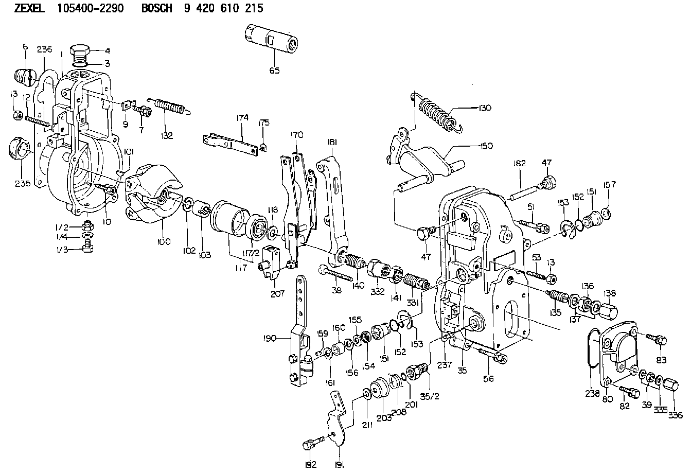
| 1. | [1] | 154000-9700 | GOVERNOR HOUSING |
| 3. | [1] | 029632-5070 | O-RING |
| 4. | [1] | 154007-2900 | CAPSULE |
| 6. | [1] | 154007-0200 | ADAPTOR |
| 7. | [1] | 020018-1840 | BLEEDER SCREW M8P1.25L18 |
| 9. | [1] | 154350-1900 | PLATE |
| 10. | [6] | 029010-6810 | BLEEDER SCREW |
| 12. | [1] | 154010-1100 | FLAT-HEAD SCREW |
| 13. | [2] | 154011-0100 | HEXAGON NUT |
| 13. | [2] | 154011-0100 | HEXAGON NUT |
| 35. | [1] | 154500-1020 | GOVERNOR COVER |
| 35/2. | [1] | 154321-0400 | BUSHING |
| 38. | [1] | 154031-2400 | FLAT-HEAD SCREW |
| 39. | [1] | 139206-0600 | UNION NUT |
| 47. | [2] | 154036-0300 | CAPSULE |
| 47. | [2] | 154036-0300 | CAPSULE |
| 51. | [2] | 020106-5040 | BLEEDER SCREW |
| 53. | [1] | 154010-0100 | FLAT-HEAD SCREW |
| 56. | [4] | 020106-3840 | BLEEDER SCREW |
| 65. | [1] | 153020-3720 | STOPPING DEVICE |
| 80. | [1] | 154063-1400 | COVER |
| 82. | [2] | 029020-6210 | BLEEDER SCREW |
| 83. | [2] | 020006-1640 | BLEEDER SCREW M6P1L16 4T |
| 100. | [1] | 154101-0020 | FLYWEIGHT ASSEMBLY |
| 101. | [1] | 025803-1610 | WOODRUFF KEY |
| 102. | [1] | 029321-2020 | LOCKING WASHER |
| 103. | [1] | 029231-2030 | UNION NUT |
| 117. | [1] | 154123-0120 | SLIDING PIECE |
| 118/1. | [0] | 029311-0010 | SHIM D14&10.1T0.2 |
| 118/1. | [0] | 029311-0180 | SHIM D14&10.1T0.3 |
| 118/1. | [0] | 029311-0190 | SHIM D14&10.1T0.40 |
| 118/1. | [0] | 029311-0210 | SHIM D14&10.1T1 |
| 118/1. | [0] | 139410-0000 | SHIM D14.0&10.1T0.5 |
| 118/1. | [0] | 139410-0100 | SHIM D14.0&10.1T1.5 |
| 118/1. | [0] | 139410-3000 | SHIM D14&10.1T2.0 |
| 118/1. | [0] | 139410-3100 | SHIM D14&10.1T3.0 |
| 118/1. | [0] | 139410-3200 | SHIM D14&10.1T4.0 |
| 130. | [1] | 154150-0400 | GOVERNOR SPRING |
| 132. | [1] | 154154-0500 | COILED SPRING |
| 135. | [1] | 154158-1320 | HEADLESS SCREW |
| 136. | [1] | 154011-1700 | UNION NUT |
| 137. | [2] | 026512-1540 | GASKET D15.4&12.2T1.50 |
| 138. | [1] | 154159-1200 | CAP NUT |
| 140. | [1] | 154185-3920 | HEADLESS SCREW |
| 141. | [1] | 029201-6010 | UNION NUT |
| 150. | [1] | 154200-7020 | SWIVELLING LEVER |
| 151. | [1] | 154204-3000 | BUSHING |
| 151. | [1] | 154204-3000 | BUSHING |
| 152. | [2] | 029631-8020 | O-RING |
| 152. | [2] | 029631-8020 | O-RING |
| 153. | [2] | 016010-1640 | LOCKING WASHER |
| 153. | [2] | 016010-1640 | LOCKING WASHER |
| 154. | [1] | 139611-0000 | PACKING RING |
| 155. | [1] | 139411-0000 | SHIM |
| 156. | [0] | 029311-1070 | SHIM D16&11T0.5 |
| 157. | [1] | 154204-3100 | BUSHING |
| 159. | [1] | 025803-1310 | WOODRUFF KEY |
| 160. | [1] | 154206-2800 | BUSHING |
| 161. | [0] | 154206-0200 | PLAIN WASHER D19.5&11.2T1.0 |
| 170. | [1] | 154210-7320 | FORK LEVER |
| 174. | [1] | 154230-3920 | STRAP |
| 175. | [1] | 016010-0540 | LOCKING WASHER |
| 181. | [1] | 154236-4100 | TENSIONING LEVER |
| 182. | [1] | 154237-0100 | BEARING PIN |
| 190. | [1] | 154301-8920 | CONTROL LEVER |
| 191. | [1] | 154364-5000 | CONTROL LEVER |
| 192. | [1] | 020006-1640 | BLEEDER SCREW M6P1L16 4T |
| 201. | [1] | 029631-0030 | O-RING &9.8W2.3 |
| 203. | [1] | 154322-0100 | CAP |
| 207. | [1] | 154326-5020 | CONTROL LEVER |
| 208. | [1] | 154327-7600 | COILED SPRING |
| 211/1. | [0] | 029311-0520 | SHIM D20.8&10.3T0.2 |
| 211/1. | [0] | 029311-0530 | SHIM D20.8&10.3T0.25 |
| 211/1. | [0] | 029311-0540 | SHIM D20.8&10.3T0.3 |
| 211/1. | [0] | 029311-0550 | SHIM D20.8&10.3T0.35 |
| 211/1. | [0] | 029311-0560 | SHIM D20.8&10.3T0.4 |
| 211/1. | [0] | 029311-0570 | SHIM D20.8&10.3T0.5 |
| 236. | [1] | 154390-1300 | GASKET |
| 237. | [1] | 154390-0300 | GASKET |
| 238. | [1] | 029635-2020 | O-RING |
| 335. | [2] | 026506-1040 | GASKET D9.9&6.2T1 |
| 336. | [1] | 154035-1600 | CAP NUT |
Cross reference number
Zexel num
Bosch num
Firm num
Name
105400-2290
223201161A HINO
GOVERNOR
K 14JB MECHANICAL GOVERNOR GOV RSV GOV
K 14JB MECHANICAL GOVERNOR GOV RSV GOV
Information:
start by:a) remove pistons1. Check to make sure that all coolant has been removed from the cylinder block.2. Put covers on the crankshaft journals for protection from dirt and water. 3. Make an adjustment of the legs on tool (A) for the length of the cylinder liner. Be careful not to damage the piston cooling tube at the bottom of the cylinder liner.4. Install tool (A) and remove the cylinder liner. 5. Remove filler band (2) and O-ring seals (1) from the cylinder liner.Install Cylinder Liners
1. Clean the cylinder liners and liner bores in the block.2. Install the liners in the block without seals or filler bands.3. Check the cylinder liner projection as follows: a) Install the 3/4"-16 NF bolts and 2F126 Washers of tooling (A) on the spacer plate around each cylinder liner as shown. Tighten the bolts evenly in four steps. 1. Tighten to a torque of 10 lb.ft. (14 N m).2. Tighten to a torque of 25 lb.ft. (35 N m).3. Tighten to a torque of 50 lb.ft. (70 N m).4. Tighten to a torque of 70 lb.ft. (95 N m).b) Put the adapter plate and one plate of tooling (A) on top of the liner and install the remainder of tooling (A). Be sure the crossbar is in position at the center of the liner. Tighten the bolts that hold tooling (A) evenly in four steps:1. Tighten to a torque of 5 lb.ft. (7 N m).2. Tighten to a torque of 15 lb.ft. (20 N m).3. Tighten to a torque of 25 lb.ft. (35 N m).4. Tighten to a torque of 50 lb.ft. (70 N m).c) Check to be sure the distance from the bottom edge of the bar to the top of the cylinder block is the same on both sides of the cylinder liner.d) Check the cylinder liner projection with tooling (B) at four locations around the cylinder liner. See the Specifications Section for the correct liner projection.
1. Clean the cylinder liners and liner bores in the block.2. Install the liners in the block without seals or filler bands.3. Check the cylinder liner projection as follows: a) Install the 3/4"-16 NF bolts and 2F126 Washers of tooling (A) on the spacer plate around each cylinder liner as shown. Tighten the bolts evenly in four steps. 1. Tighten to a torque of 10 lb.ft. (14 N m).2. Tighten to a torque of 25 lb.ft. (35 N m).3. Tighten to a torque of 50 lb.ft. (70 N m).4. Tighten to a torque of 70 lb.ft. (95 N m).b) Put the adapter plate and one plate of tooling (A) on top of the liner and install the remainder of tooling (A). Be sure the crossbar is in position at the center of the liner. Tighten the bolts that hold tooling (A) evenly in four steps:1. Tighten to a torque of 5 lb.ft. (7 N m).2. Tighten to a torque of 15 lb.ft. (20 N m).3. Tighten to a torque of 25 lb.ft. (35 N m).4. Tighten to a torque of 50 lb.ft. (70 N m).c) Check to be sure the distance from the bottom edge of the bar to the top of the cylinder block is the same on both sides of the cylinder liner.d) Check the cylinder liner projection with tooling (B) at four locations around the cylinder liner. See the Specifications Section for the correct liner projection.