Information governor
BOSCH
F 019 Z9E 437
f019z9e437
ZEXEL
105400-2270
1054002270
NISSAN-DIESEL
19200Z5605
19200z5605
Rating:
Scheme ###:
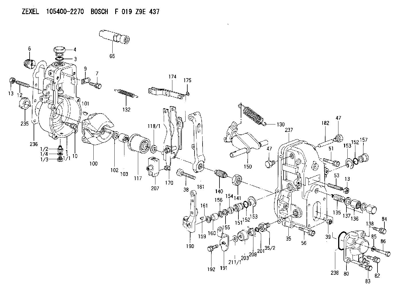
| 1. | [1] | 154000-3820 | GOVERNOR HOUSING |
| 1/1. | [1] | 154000-3800 | GOVERNOR HOUSING |
| 1/2. | [1] | 155012-0700 | ADAPTOR |
| 1/3. | [1] | 029010-6010 | CAPSULE M6P1.0L7 |
| 1/4. | [1] | 026506-1040 | GASKET D9.9&6.2T1 |
| 3. | [1] | 029632-5070 | O-RING |
| 4. | [1] | 154007-2900 | CAPSULE |
| 6. | [1] | 154007-0200 | ADAPTOR |
| 7. | [1] | 020018-1840 | BLEEDER SCREW M8P1.25L18 |
| 9. | [1] | 154350-1900 | PLATE |
| 10. | [6] | 029010-6810 | BLEEDER SCREW |
| 12. | [1] | 154010-0100 | FLAT-HEAD SCREW |
| 13. | [2] | 154011-0100 | HEXAGON NUT |
| 13. | [2] | 154011-0100 | HEXAGON NUT |
| 35. | [1] | 154500-1020 | GOVERNOR COVER |
| 35/2. | [1] | 154321-0400 | BUSHING |
| 38. | [1] | 154031-0100 | FLAT-HEAD SCREW |
| 39. | [1] | 013020-6020 | UNION NUT M6P1H5 |
| 47. | [2] | 154036-0300 | CAPSULE |
| 47. | [2] | 154036-0300 | CAPSULE |
| 51. | [2] | 020106-5040 | BLEEDER SCREW |
| 53. | [1] | 154010-0200 | FLAT-HEAD SCREW |
| 56. | [4] | 020106-3840 | BLEEDER SCREW |
| 65. | [1] | 153020-0320 | STOPPING DEVICE |
| 80. | [1] | 154063-1220 | COVER |
| 82. | [1] | 029020-6210 | BLEEDER SCREW |
| 83. | [1] | 029020-6210 | BLEEDER SCREW |
| 84. | [1] | 010006-3840 | BLEEDER SCREW |
| 85. | [1] | 014110-6440 | LOCKING WASHER |
| 86. | [1] | 020006-1640 | BLEEDER SCREW M6P1L16 4T |
| 100. | [1] | 154100-4520 | FLYWEIGHT ASSEMBLY |
| 101. | [1] | 025803-1610 | WOODRUFF KEY |
| 102. | [1] | 029321-2020 | LOCKING WASHER |
| 103. | [1] | 029231-2030 | UNION NUT |
| 117. | [1] | 154123-0120 | SLIDING PIECE |
| 118/1. | [0] | 029311-0010 | SHIM D14&10.1T0.2 |
| 118/1. | [0] | 029311-0180 | SHIM D14&10.1T0.3 |
| 118/1. | [0] | 029311-0190 | SHIM D14&10.1T0.40 |
| 118/1. | [0] | 029311-0210 | SHIM D14&10.1T1 |
| 118/1. | [0] | 139410-0000 | SHIM D14.0&10.1T0.5 |
| 118/1. | [0] | 139410-0100 | SHIM D14.0&10.1T1.5 |
| 118/1. | [0] | 139410-3000 | SHIM D14&10.1T2.0 |
| 118/1. | [0] | 139410-3100 | SHIM D14&10.1T3.0 |
| 118/1. | [0] | 139410-3200 | SHIM D14&10.1T4.0 |
| 130. | [1] | 154150-2700 | GOVERNOR SPRING |
| 132. | [1] | 154154-0500 | COILED SPRING |
| 135. | [1] | 154157-5520 | HEADLESS SCREW |
| 136. | [1] | 029201-2030 | UNION NUT M12P1.0H4 |
| 137. | [2] | 026512-1540 | GASKET D15.4&12.2T1.50 |
| 138. | [1] | 154159-1200 | CAP NUT |
| 140. | [1] | 154177-1520 | HEADLESS SCREW |
| 141. | [1] | 029201-6010 | UNION NUT |
| 150. | [1] | 154200-7120 | SWIVELLING LEVER |
| 151. | [1] | 154204-4300 | BUSHING |
| 152. | [2] | 029631-8020 | O-RING |
| 152. | [2] | 029631-8020 | O-RING |
| 153. | [2] | 016010-1640 | LOCKING WASHER |
| 153. | [2] | 016010-1640 | LOCKING WASHER |
| 154. | [1] | 139611-0000 | PACKING RING |
| 155. | [1] | 139411-0000 | SHIM |
| 156. | [0] | 029311-1070 | SHIM D16&11T0.5 |
| 157. | [1] | 154204-4400 | BUSHING |
| 159. | [1] | 025803-1310 | WOODRUFF KEY |
| 160. | [1] | 154206-2800 | BUSHING |
| 161. | [0] | 154206-0200 | PLAIN WASHER D19.5&11.2T1.0 |
| 170. | [1] | 154210-0920 | FORK LEVER |
| 174. | [1] | 154230-3920 | STRAP |
| 175. | [1] | 016010-0540 | LOCKING WASHER |
| 181. | [1] | 154236-1500 | TENSIONING LEVER |
| 182. | [1] | 154237-0100 | BEARING PIN |
| 190. | [1] | 154309-6120 | CONTROL LEVER |
| 191. | [1] | 154364-1400 | CONTROL LEVER |
| 192. | [1] | 020006-1640 | BLEEDER SCREW M6P1L16 4T |
| 201. | [1] | 029631-0030 | O-RING &9.8W2.3 |
| 203. | [1] | 154322-0100 | CAP |
| 207. | [1] | 154326-5020 | CONTROL LEVER |
| 208. | [1] | 154327-7600 | COILED SPRING |
| 211/1. | [0] | 029311-0520 | SHIM D20.8&10.3T0.2 |
| 211/1. | [0] | 029311-0530 | SHIM D20.8&10.3T0.25 |
| 211/1. | [0] | 029311-0540 | SHIM D20.8&10.3T0.3 |
| 211/1. | [0] | 029311-0550 | SHIM D20.8&10.3T0.35 |
| 211/1. | [0] | 029311-0560 | SHIM D20.8&10.3T0.4 |
| 211/1. | [0] | 029311-0570 | SHIM D20.8&10.3T0.5 |
| 235. | [1] | 155412-5200 | IMPELLER WHEEL |
| 236. | [1] | 154390-0000 | GASKET |
| 237. | [1] | 154390-0300 | GASKET |
| 238. | [1] | 029635-2020 | O-RING |
Include in #1:
101691-9210
as GOVERNOR
Cross reference number
Zexel num
Bosch num
Firm num
Name
105400-2270
F 019 Z9E 437
19200Z5605 NISSAN-DIESEL
GOVERNOR
* K
* K
Information:
start by:a) remove oil pump1. Check the identification on the connecting rods and caps as to their location in the engine. The caps must be installed in original positions in the engine.2. Turn the crankshaft until two of the pistons are at bottom center. 3. Remove connecting rod caps (1) from the connecting rods. Remove the lower half of the bearings from the caps.
Be careful not to damage the crankshaft journals. Do not turn the crankshaft while any of the connecting rod caps are removed.
4. Push the connecting rod away from the crankshaft and remove the upper half of the bearings from the connecting rods.5. Make sure the surface of the connecting rod where the bearings make contact is clean and free of dirt.
Make sure the tabs on the bearings are in alignment with the notches in the connecting rods and caps.
6. Install the upper half of new bearings in the connecting rods.7. Pull the connecting rod down slowly on the crankshaft.
Make sure the surfaces where the bearings make contact in the caps are clean and free of dirt.
8. Install new bearings (2) in the caps. Make sure the tabs on the bearings are in alignment with the notches in the caps.9. Put clean engine oil on the threads of the bolts in the connecting rods.10. Check the bearing clearance with Plastigage (A) as follows: a) Make sure the numbers on the caps and connecting rods are the same and are on the same respective side. If new connecting rods are installed, put the cylinder number on the rods and caps.b) Put the caps and plastigage (A) in the correct position on the connecting rods. Install the nuts that hold them.c) Tighten the two nuts evenly to a torque of 60 6 lb.ft. (81.3 8.1 N m). Put a mark on each nut and tighten the nuts 120° more from the marks. d) Remove the caps from the connecting rods and Plastigage (A). Measure the thickness of the Plastigage. The connecting rod bearing clearance must be .0028 to .0066 in. (0.071 to 0.168 mm) for new bearings.e) Put clean engine oil in the bearing caps and install them again. Follow the tightening procedure in Step 10.f) Do Steps 1 through 10 for the other connecting rod bearings.end by:a) install oil pump
Have questions with 105400-2270?
Group cross 105400-2270 ZEXEL
Hino
Nissan-Diesel
Yanmar
Nissan-Diesel
105400-2270
F 019 Z9E 437
19200Z5605
GOVERNOR