Information governor
BOSCH
9 420 612 730
9420612730
ZEXEL
105400-2250
1054002250
YANMAR
12765061550
12765061550
Rating:
Scheme ###:
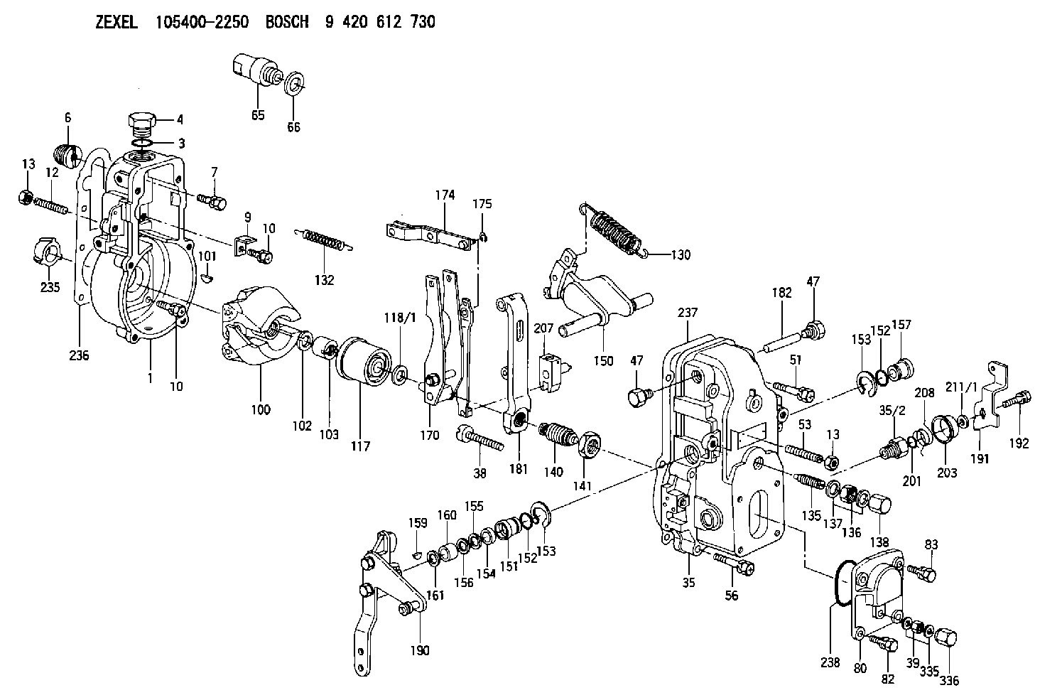
| 1. | [1] | 154000-6300 | GOVERNOR HOUSING |
| 3. | [1] | 029632-5070 | O-RING |
| 4. | [1] | 154007-2900 | CAPSULE |
| 6. | [1] | 154007-0200 | ADAPTOR |
| 7. | [1] | 020018-1840 | BLEEDER SCREW M8P1.25L18 |
| 9. | [1] | 154350-1900 | PLATE |
| 9. | [1] | 154350-1900 | PLATE |
| 10. | [6] | 029010-6810 | BLEEDER SCREW |
| 12. | [1] | 154010-1100 | FLAT-HEAD SCREW |
| 13. | [2] | 154011-0100 | HEXAGON NUT |
| 13. | [2] | 154011-0100 | HEXAGON NUT |
| 35. | [1] | 154500-3020 | GOVERNOR COVER |
| 35/2. | [1] | 154321-0400 | BUSHING |
| 38. | [1] | 154031-2400 | FLAT-HEAD SCREW |
| 39. | [1] | 139206-0600 | UNION NUT |
| 47. | [2] | 154036-0300 | CAPSULE |
| 47. | [2] | 154036-0300 | CAPSULE |
| 51. | [2] | 020106-5040 | BLEEDER SCREW |
| 53. | [1] | 154010-0100 | FLAT-HEAD SCREW |
| 56. | [4] | 020106-3840 | BLEEDER SCREW |
| 65. | [1] | 154050-1720 | STOPPING DEVICE |
| 66. | [1] | 026518-2240 | GASKET D21.9&18.2T1 |
| 80. | [1] | 154063-1400 | COVER |
| 82. | [2] | 029020-6210 | BLEEDER SCREW |
| 83. | [2] | 020006-1640 | BLEEDER SCREW M6P1L16 4T |
| 100. | [1] | 154100-2320 | FLYWEIGHT ASSEMBLY |
| 101. | [1] | 025803-1610 | WOODRUFF KEY |
| 102. | [1] | 029321-2020 | LOCKING WASHER |
| 103. | [1] | 029231-2030 | UNION NUT |
| 117. | [1] | 154123-0120 | SLIDING PIECE |
| 118/1. | [0] | 029311-0010 | SHIM D14&10.1T0.2 |
| 118/1. | [0] | 029311-0180 | SHIM D14&10.1T0.3 |
| 118/1. | [0] | 029311-0190 | SHIM D14&10.1T0.40 |
| 118/1. | [0] | 029311-0210 | SHIM D14&10.1T1 |
| 118/1. | [0] | 139410-0000 | SHIM D14.0&10.1T0.5 |
| 118/1. | [0] | 139410-0100 | SHIM D14.0&10.1T1.5 |
| 118/1. | [0] | 139410-3000 | SHIM D14&10.1T2.0 |
| 118/1. | [0] | 139410-3100 | SHIM D14&10.1T3.0 |
| 118/1. | [0] | 139410-3200 | SHIM D14&10.1T4.0 |
| 130. | [1] | 154150-2900 | GOVERNOR SPRING |
| 132. | [1] | 154154-0800 | COILED SPRING |
| 135. | [1] | 154157-0120 | HEADLESS SCREW |
| 136. | [1] | 029201-2030 | UNION NUT M12P1.0H4 |
| 137. | [2] | 026512-1540 | GASKET D15.4&12.2T1.50 |
| 138. | [1] | 154159-1200 | CAP NUT |
| 140. | [1] | 154177-0520 | HEADLESS SCREW |
| 141. | [1] | 029201-6010 | UNION NUT |
| 150. | [1] | 154200-7020 | SWIVELLING LEVER |
| 151. | [1] | 154204-4300 | BUSHING |
| 152. | [2] | 029631-8020 | O-RING |
| 152. | [2] | 029631-8020 | O-RING |
| 153. | [2] | 016010-1640 | LOCKING WASHER |
| 153. | [2] | 016010-1640 | LOCKING WASHER |
| 154. | [1] | 139611-0000 | PACKING RING |
| 155. | [1] | 139411-0000 | SHIM |
| 156. | [0] | 029311-1070 | SHIM D16&11T0.5 |
| 157. | [1] | 154204-4400 | BUSHING |
| 159. | [1] | 025803-1310 | WOODRUFF KEY |
| 160. | [1] | 154206-2800 | BUSHING |
| 161. | [0] | 154206-0200 | PLAIN WASHER D19.5&11.2T1.0 |
| 170. | [1] | 154211-3920 | FORK LEVER |
| 174. | [1] | 154230-3920 | STRAP |
| 175. | [1] | 016010-0540 | LOCKING WASHER |
| 181. | [1] | 154236-4100 | TENSIONING LEVER |
| 182. | [1] | 154237-0100 | BEARING PIN |
| 190. | [1] | 154345-5320 | CONTROL LEVER |
| 191. | [1] | 154304-2800 | CONTROL LEVER |
| 192. | [1] | 020006-1640 | BLEEDER SCREW M6P1L16 4T |
| 201. | [1] | 029631-0030 | O-RING &9.8W2.3 |
| 203. | [1] | 154322-0100 | CAP |
| 207. | [1] | 154326-5120 | CONTROL LEVER |
| 208. | [1] | 154327-7300 | COILED SPRING |
| 211/1. | [0] | 029311-0520 | SHIM D20.8&10.3T0.2 |
| 211/1. | [0] | 029311-0530 | SHIM D20.8&10.3T0.25 |
| 211/1. | [0] | 029311-0540 | SHIM D20.8&10.3T0.3 |
| 211/1. | [0] | 029311-0550 | SHIM D20.8&10.3T0.35 |
| 211/1. | [0] | 029311-0560 | SHIM D20.8&10.3T0.4 |
| 211/1. | [0] | 029311-0570 | SHIM D20.8&10.3T0.5 |
| 235. | [1] | 155412-5200 | IMPELLER WHEEL |
| 236. | [1] | 154390-0000 | GASKET |
| 237. | [1] | 154390-0300 | GASKET |
| 238. | [1] | 029635-2020 | O-RING |
| 335. | [2] | 026506-1040 | GASKET D9.9&6.2T1 |
| 336. | [1] | 154035-1600 | CAP NUT |
Cross reference number
Zexel num
Bosch num
Firm num
Name
105400-2250
12765061550 YANMAR
GOVERNOR
K 14JB MECHANICAL GOVERNOR GOV RSV GOV
K 14JB MECHANICAL GOVERNOR GOV RSV GOV
Information:
start by:a) remove pistons 1. Remove bearings (3) from the connecting rod and connecting rod cap.2. Remove retainer ring (1) with tool (A).3. Remove pin (2) and connecting rod (4) from the piston. 4. Remove the piston rings (5) from the piston with tool (B). Clean the piston ring grooves on the pistons with an acceptable ring groove cleaning tool. See USE OF PISTON PIN BEARING REMOVAL AND INSTALLATION TOOLS, SPECIAL INSTRUCTIONS, Form No. SMHS7295.5. Heat the connecting rod (4) in an oven to a temperature of 350°-500°F (177°-260°C). Never use a direct flame to heat a connecting rod. 6. Put connecting rod (4) in position on the base plate of tooling (C). Put a new rod pin bearing (6) on the adapter part of tooling (C). The old bearing is pushed out by tooling (C) as the new bearing is installed.7. Use tooling (C) to push the new bearing into the connecting rod until the push adapter of tooling (C) makes full contact with the connecting rod surface.8. Use a pin boring machine to make the rod pin bearing the correct size. The bore in the new rod pin bearing must be 2.0012 .0003 in. (50.830 0.008 mm).9. Check the clearance between the ends of the piston rings. See PISTONS AND RINGS in SPECIFICATIONS.10. Install the oil ring spring in the oil ring groove of the piston. The oil ring is to be installed over the spring with the oil ring end gap 180° from the oil ring spring joint. 11. Install the oil ring on the piston with tool (B).12. Install the second (intermediate) piston ring with the side that has the identification "UP-2" toward the top of the piston with tool (B).13. Install the first (top) piston ring with the side that has the identification "UP-1" toward the top of the piston with tool (B). After the installation of all three piston rings, put the piston rings in position so the end gaps are 120° apart. 14. Put the piston in position on connecting rod (4). Put clean engine oil on pin (2) and install the pin. Install retainer rings (1) with tool (A). Make sure the retainer rings are in the grooves of the piston.15. Install bearings (3) in the connecting rod and connecting rod cap.end by:a) install pistons