Information governor
BOSCH
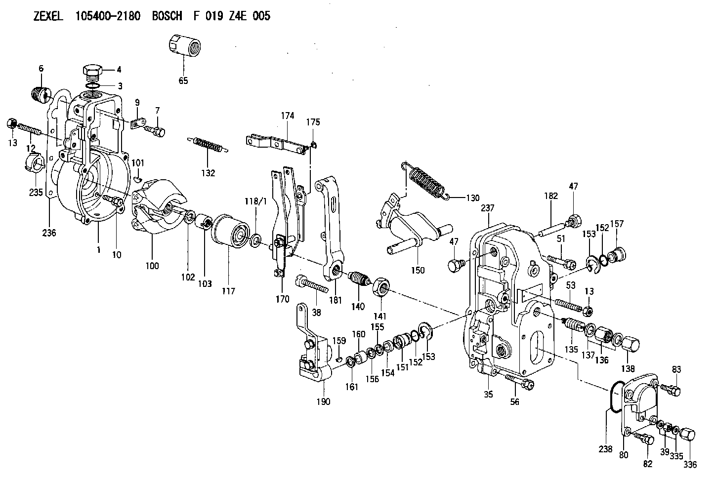
F 019 Z4E 005
f019z4e005
ZEXEL
105400-2180
1054002180
Rating:
Scheme ###:
| 1. | [1] | 154000-6300 | GOVERNOR HOUSING |
| 3. | [1] | 029632-5070 | O-RING |
| 4. | [1] | 154007-2900 | CAPSULE |
| 6. | [1] | 154007-0200 | ADAPTOR |
| 7. | [1] | 020018-1840 | BLEEDER SCREW M8P1.25L18 |
| 9. | [1] | 154350-1900 | PLATE |
| 10. | [6] | 029010-6810 | BLEEDER SCREW |
| 12. | [1] | 154010-0100 | FLAT-HEAD SCREW |
| 13. | [2] | 154011-0100 | HEXAGON NUT |
| 13. | [2] | 154011-0100 | HEXAGON NUT |
| 35. | [1] | 154500-0020 | GOVERNOR COVER |
| 38. | [1] | 154031-2400 | FLAT-HEAD SCREW |
| 39. | [1] | 139206-0600 | UNION NUT |
| 47. | [2] | 154036-0300 | CAPSULE |
| 47. | [2] | 154036-0300 | CAPSULE |
| 51. | [2] | 020106-5040 | BLEEDER SCREW |
| 53. | [1] | 154010-0300 | FLAT-HEAD SCREW |
| 56. | [4] | 020106-3840 | BLEEDER SCREW |
| 65. | [1] | 155404-3700 | CAP |
| 80. | [1] | 154063-1400 | COVER |
| 82. | [2] | 029020-6210 | BLEEDER SCREW |
| 83. | [2] | 020006-1640 | BLEEDER SCREW M6P1L16 4T |
| 100. | [1] | 154100-3220 | FLYWEIGHT ASSEMBLY |
| 100. | [1] | 154100-9720 | FLYWEIGHT ASSEMBLY |
| 101. | [1] | 025803-1610 | WOODRUFF KEY |
| 102. | [1] | 029321-2020 | LOCKING WASHER |
| 103. | [1] | 029231-2030 | UNION NUT |
| 117. | [1] | 154123-0120 | SLIDING PIECE |
| 118/1. | [0] | 029311-0010 | SHIM D14&10.1T0.2 |
| 118/1. | [0] | 029311-0180 | SHIM D14&10.1T0.3 |
| 118/1. | [0] | 029311-0190 | SHIM D14&10.1T0.40 |
| 118/1. | [0] | 029311-0210 | SHIM D14&10.1T1 |
| 118/1. | [0] | 139410-0000 | SHIM D14.0&10.1T0.5 |
| 118/1. | [0] | 139410-0100 | SHIM D14.0&10.1T1.5 |
| 118/1. | [0] | 139410-3000 | SHIM D14&10.1T2.0 |
| 118/1. | [0] | 139410-3100 | SHIM D14&10.1T3.0 |
| 118/1. | [0] | 139410-3200 | SHIM D14&10.1T4.0 |
| 130. | [1] | 154150-2900 | GOVERNOR SPRING |
| 132. | [1] | 154154-0800 | COILED SPRING |
| 135. | [1] | 154158-0820 | HEADLESS SCREW |
| 136. | [1] | 154011-1700 | UNION NUT |
| 137. | [2] | 026512-1540 | GASKET D15.4&12.2T1.50 |
| 138. | [1] | 154159-1200 | CAP NUT |
| 140. | [1] | 154178-8020 | HEADLESS SCREW |
| 141. | [1] | 029201-6010 | UNION NUT |
| 150. | [1] | 154200-7020 | SWIVELLING LEVER |
| 151. | [1] | 154204-4300 | BUSHING |
| 152. | [2] | 029631-8020 | O-RING |
| 152. | [2] | 029631-8020 | O-RING |
| 153. | [2] | 016010-1640 | LOCKING WASHER |
| 153. | [2] | 016010-1640 | LOCKING WASHER |
| 154. | [1] | 139611-0000 | PACKING RING |
| 155. | [1] | 139411-0000 | SHIM |
| 156. | [0] | 029311-1070 | SHIM D16&11T0.5 |
| 157. | [1] | 154204-4400 | BUSHING |
| 159. | [1] | 025803-1310 | WOODRUFF KEY |
| 160. | [1] | 154206-2800 | BUSHING |
| 161. | [0] | 154206-0200 | PLAIN WASHER D19.5&11.2T1.0 |
| 170. | [1] | 154211-3720 | FORK LEVER |
| 174. | [1] | 154230-0120 | STRAP |
| 175. | [1] | 016010-0540 | LOCKING WASHER |
| 181. | [1] | 154236-4100 | TENSIONING LEVER |
| 182. | [1] | 154237-0100 | BEARING PIN |
| 190. | [1] | 154309-4420 | CONTROL LEVER |
| 235. | [1] | 155412-5200 | IMPELLER WHEEL |
| 236. | [1] | 154390-0000 | GASKET |
| 237. | [1] | 154390-0300 | GASKET |
| 238. | [1] | 029635-2020 | O-RING |
| 335. | [2] | 026506-1040 | GASKET D9.9&6.2T1 |
| 336. | [1] | 154035-1600 | CAP NUT |
Include in #1:
101402-3452
as GOVERNOR
Cross reference number
Zexel num
Bosch num
Firm num
Name
Information:
2. Remove oil filter base support (2), air line (3) and oil level gauge tube (4). Remove the right lifting eye (1) and the left lifting eye. 3. Remove glow plug leads (5) and the 3/8 in. bolts from the cylinder head. Glow plug leads are on the precombustion engine only.4. Install two 5/16"-18 NC forged eyebolts and nuts in the cylinder head. Fasten a hoist to the cylinder head.5. Remove cylinder head bolts (6) and the washers. Clean all debris or foreign material from the "V" of the engine before removal of the cylinder head.6. Remove the cylinder head. Weight of the cylinder head is 200 lb. (90 kg). Put a cover over the intake manifold portion of the cylinder head to keep dirt and foreign material out.
Do not put the cylinder head down on a flat surface. This can cause damage to the fuel injection valves.
A new spacer plate gasket must be installed when the cylinder head is removed. See REMOVE AND INSTALL SPACER PLATE.Install Cylinder Head
1. Clean the spacer plate and the bottom surface of the cylinder head. Put a new cylinder head gasket (3) and seals (4) in position on the spacer plate as shown.2. Fasten a hoist to cylinder head (2) and put it in position over dowels (5) in the cylinder block.3. Put clean SAE 30 oil on the threads of the bolts that hold the cylinder head in position. Install the bolts and washers and tighten them to the correct torque as follows: a) Tighten bolts 1 through 14 in number sequence to a torque of 200 20 lb.ft. (270 25 N m).b) Tighten bolts 1 through 14 in number sequence to a torque of 330 15 lb.ft. (447 20 N m).c) Tighten bolts 1 through 14 again in number sequence to a torque of 330 15 lb.ft. (447 20 N m).d) Install the rocker shaft assembly and push rods.e) Tighten bolts 15 through 18 in number sequence to a torque of 200 20 lb.ft. (270 25 N m).f) Tighten bolts 15 through 18 in number sequence to a torque of 330 15 lb.ft. (447 20 N m).g) Tighten bolts 15 through 18 again in number sequence to a torque of 330 15 lb.ft. (447 20 N m).4. Install the glow plug leads and the 3/8 in. bolts in the cylinder head. Tighten the bolts to a torque of 32 5 lb.ft. (43 7 N m). If studs (1) were removed, install new studs and tighten them to a torque of 20 3 lb.ft. (25 4 N m).5. Make an adjustment for the valve clearance. The clearance must be .015 .003 in. (0.38 0.07 mm) for intake and .030 .003 in. (0.76 0.07 mm) for exhaust. See VALVE CLEARANCE SETTING in TESTING AND ADJUSTING.6. Install the left and right lifting eyes.7. Install the oil level gauge tube, air line and oil