Information governor
BOSCH
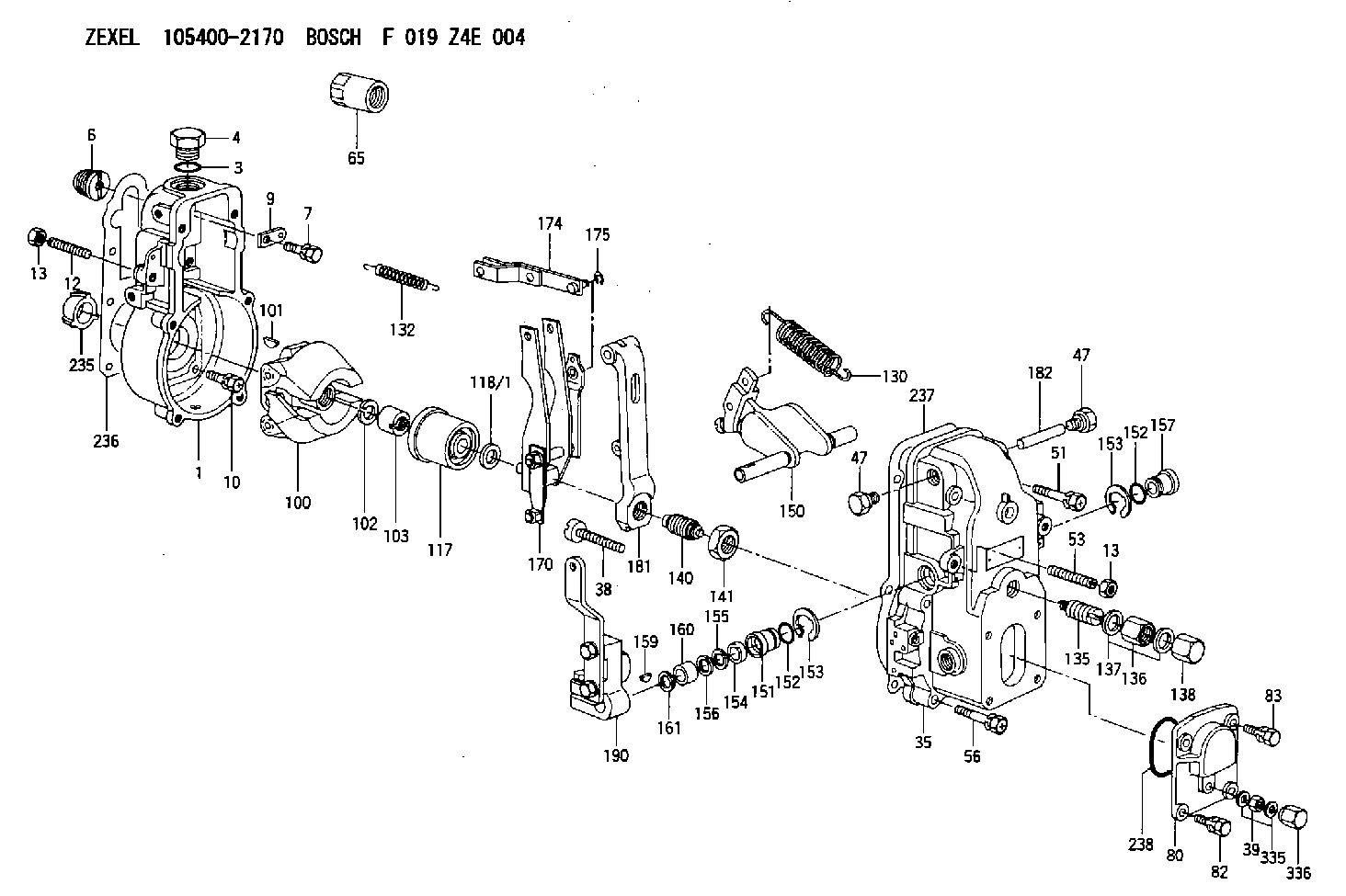
F 019 Z4E 004
f019z4e004
ZEXEL
105400-2170
1054002170
Rating:
Scheme ###:
| 1. | [1] | 154000-6300 | GOVERNOR HOUSING |
| 3. | [1] | 029632-5070 | O-RING |
| 4. | [1] | 154007-2900 | CAPSULE |
| 6. | [1] | 154007-0200 | ADAPTOR |
| 7. | [1] | 020018-1840 | BLEEDER SCREW M8P1.25L18 |
| 9. | [1] | 154350-1900 | PLATE |
| 10. | [6] | 029010-6810 | BLEEDER SCREW |
| 12. | [1] | 154010-0100 | FLAT-HEAD SCREW |
| 13. | [2] | 154011-0100 | HEXAGON NUT |
| 13. | [2] | 154011-0100 | HEXAGON NUT |
| 35. | [1] | 154500-0020 | GOVERNOR COVER |
| 38. | [1] | 154031-2400 | FLAT-HEAD SCREW |
| 39. | [1] | 139206-0600 | UNION NUT |
| 47. | [2] | 154036-0300 | CAPSULE |
| 47. | [2] | 154036-0300 | CAPSULE |
| 51. | [2] | 020106-5040 | BLEEDER SCREW |
| 53. | [1] | 154010-0300 | FLAT-HEAD SCREW |
| 56. | [4] | 020106-3840 | BLEEDER SCREW |
| 65. | [1] | 155404-3700 | CAP |
| 80. | [1] | 154063-1400 | COVER |
| 82. | [2] | 029020-6210 | BLEEDER SCREW |
| 83. | [2] | 020006-1640 | BLEEDER SCREW M6P1L16 4T |
| 100. | [1] | 154100-3220 | FLYWEIGHT ASSEMBLY |
| 101. | [1] | 025803-1610 | WOODRUFF KEY |
| 102. | [1] | 029321-2020 | LOCKING WASHER |
| 103. | [1] | 029231-2030 | UNION NUT |
| 117. | [1] | 154123-0120 | SLIDING PIECE |
| 118/1. | [0] | 029311-0010 | SHIM D14&10.1T0.2 |
| 118/1. | [0] | 029311-0180 | SHIM D14&10.1T0.3 |
| 118/1. | [0] | 029311-0190 | SHIM D14&10.1T0.40 |
| 118/1. | [0] | 029311-0210 | SHIM D14&10.1T1 |
| 118/1. | [0] | 139410-0000 | SHIM D14.0&10.1T0.5 |
| 118/1. | [0] | 139410-0100 | SHIM D14.0&10.1T1.5 |
| 118/1. | [0] | 139410-3000 | SHIM D14&10.1T2.0 |
| 118/1. | [0] | 139410-3100 | SHIM D14&10.1T3.0 |
| 118/1. | [0] | 139410-3200 | SHIM D14&10.1T4.0 |
| 130. | [1] | 154150-2900 | GOVERNOR SPRING |
| 132. | [1] | 154154-0701 | COILED SPRING |
| 135. | [1] | 154158-0820 | HEADLESS SCREW |
| 136. | [1] | 154011-1700 | UNION NUT |
| 137. | [2] | 026512-1540 | GASKET D15.4&12.2T1.50 |
| 138. | [1] | 154159-1200 | CAP NUT |
| 140. | [1] | 154175-0820 | HEADLESS SCREW |
| 141. | [1] | 029201-6010 | UNION NUT |
| 150. | [1] | 154200-7020 | SWIVELLING LEVER |
| 151. | [1] | 154204-3000 | BUSHING |
| 152. | [2] | 029631-8020 | O-RING |
| 152. | [2] | 029631-8020 | O-RING |
| 153. | [2] | 016010-1640 | LOCKING WASHER |
| 153. | [2] | 016010-1640 | LOCKING WASHER |
| 154. | [1] | 139611-0000 | PACKING RING |
| 155. | [1] | 139411-0000 | SHIM |
| 156. | [0] | 029311-1090 | SHIM D16&11T0.3 |
| 157. | [1] | 154204-3100 | BUSHING |
| 159. | [1] | 025803-1310 | WOODRUFF KEY |
| 160. | [1] | 154206-2800 | BUSHING |
| 161. | [0] | 154206-0200 | PLAIN WASHER D19.5&11.2T1.0 |
| 170. | [1] | 154211-3720 | FORK LEVER |
| 174. | [1] | 154230-0120 | STRAP |
| 175. | [1] | 016010-0540 | LOCKING WASHER |
| 181. | [1] | 154236-4100 | TENSIONING LEVER |
| 182. | [1] | 154237-0100 | BEARING PIN |
| 190. | [1] | 154309-4420 | CONTROL LEVER |
| 235. | [1] | 155412-5200 | IMPELLER WHEEL |
| 236. | [1] | 154390-0000 | GASKET |
| 237. | [1] | 154390-0300 | GASKET |
| 238. | [1] | 029635-2020 | O-RING |
| 335. | [2] | 026506-1040 | GASKET D9.9&6.2T1 |
| 336. | [1] | 154035-1600 | CAP NUT |
Include in #1:
101402-3442
as GOVERNOR
Cross reference number
Zexel num
Bosch num
Firm num
Name
105400-2170
F 019 Z4E 004
GOVERNOR
* K
* K
Information:
start by:a) remove timing gear coverb) remove valve lifters1. Remove the turbocharger drain tube from the flywheel housing. 2. Remove two studs (1) from the flywheel housing. 3. Turn the engine with tool (B). Remove the four bolts from rear camshaft gear (2).
Tooling (A) must be used to prevent the loss of timing of the rear balance weight gear and to keep the rear camshaft gear in place when the camshaft is removed.
4. Install tooling (A) in the flywheel housing. Turn the engine until bolts (3) of tooling (A) engage in the bolt hole of the gear. The two bolts in the rear camshaft gear keep correct timing with the rear balance weight gear.5. Evenly tighten the two bolts (3) to free the gear from the camshaft. 6. Remove two bolts (4) and the thrust plate from front of the engine and camshaft. If necessary, use a driver and hammer to give more impact load on the camshaft gear as follows:a) Loosen tooling (A) to release pressure from the rear camshaft and gear.b) Remove the thrust plate from the front engine block and camshaft.c) Evenly tighten tooling (A) again.d) Use the driver and hammer to free the rear gear from the camshaft taper. 7. Remove camshaft (5) from the front of the engine block.
Be careful not to cause damage to the camshaft bearings.
Install Camshaft
1. Put clean SAE 30 engine oil on the lobes and journals of the camshaft. 2. Install camshaft (1) in the cylinder block with front camshaft gear "V" mark (3) in alignment with the idler and balance weight gear "V" mark. 3. Install thrust plate (2) and the bolts to the front of the engine that hold the camshaft in position. 4. Loosen bolts (5) of tooling (A) from the rear camshaft gear (4) to make alignment of camshaft dowel with the dowel hole in the gear. Install the gear on the camshaft. 5. Install one bolt (6) to hold the gear to the camshaft. Remove tooling (A) from the camshaft gear and flywheel housing.6. Turn the engine with tool (B) and install the remainder of the bolts that hold the gear to the camshaft. Tighten the bolts to a torque of 20 3 lb.ft. (25 4 N m).7. Install the two studs and the turbocharger drain tube to the flywheel housing.end by:a) install valve liftersb) install timing gear cover
Have questions with 105400-2170?
Group cross 105400-2170 ZEXEL
Hino
Yanmar
105400-2170
F 019 Z4E 004
GOVERNOR