Information governor
BOSCH
9 420 611 540
9420611540
ZEXEL
105400-2150
1054002150
YANMAR
12745061550
12745061550
Rating:
Scheme ###:
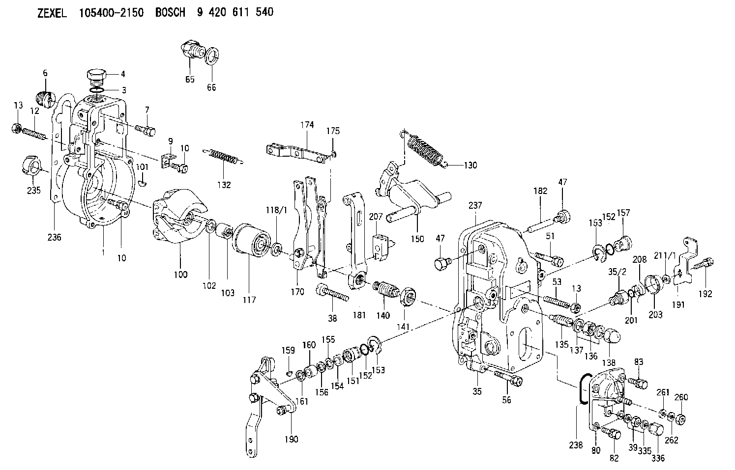
| 1. | [1] | 154000-6300 | GOVERNOR HOUSING |
| 3. | [1] | 029632-5070 | O-RING |
| 4. | [1] | 154007-2900 | CAPSULE |
| 6. | [1] | 154007-0200 | ADAPTOR |
| 7. | [1] | 020018-1840 | BLEEDER SCREW M8P1.25L18 |
| 9. | [1] | 154350-1900 | PLATE |
| 10. | [6] | 029010-6810 | BLEEDER SCREW |
| 10. | [6] | 029010-6810 | BLEEDER SCREW |
| 12. | [1] | 154010-1100 | FLAT-HEAD SCREW |
| 13. | [2] | 154011-0100 | HEXAGON NUT |
| 13. | [2] | 154011-0100 | HEXAGON NUT |
| 35. | [1] | 154500-3020 | GOVERNOR COVER |
| 35/2. | [1] | 154321-0400 | BUSHING |
| 38. | [1] | 154031-2400 | FLAT-HEAD SCREW |
| 39. | [1] | 139206-0600 | UNION NUT |
| 47. | [2] | 154036-0300 | CAPSULE |
| 47. | [2] | 154036-0300 | CAPSULE |
| 51. | [2] | 020106-5040 | BLEEDER SCREW |
| 53. | [1] | 154010-0100 | FLAT-HEAD SCREW |
| 56. | [4] | 020106-3840 | BLEEDER SCREW |
| 65. | [1] | 153020-4420 | STOPPING DEVICE |
| 66. | [1] | 026518-2240 | GASKET D21.9&18.2T1 |
| 80. | [1] | 154063-4520 | COVER |
| 82. | [2] | 029020-6210 | BLEEDER SCREW |
| 83. | [2] | 020006-1640 | BLEEDER SCREW M6P1L16 4T |
| 100. | [1] | 154100-2320 | FLYWEIGHT ASSEMBLY |
| 101. | [1] | 025803-1610 | WOODRUFF KEY |
| 102. | [1] | 029321-2020 | LOCKING WASHER |
| 103. | [1] | 029231-2030 | UNION NUT |
| 117. | [1] | 154123-0120 | SLIDING PIECE |
| 118/1. | [0] | 029311-0010 | SHIM D14&10.1T0.2 |
| 118/1. | [0] | 029311-0180 | SHIM D14&10.1T0.3 |
| 118/1. | [0] | 029311-0190 | SHIM D14&10.1T0.40 |
| 118/1. | [0] | 029311-0210 | SHIM D14&10.1T1 |
| 118/1. | [0] | 139410-0000 | SHIM D14.0&10.1T0.5 |
| 118/1. | [0] | 139410-0100 | SHIM D14.0&10.1T1.5 |
| 118/1. | [0] | 139410-3000 | SHIM D14&10.1T2.0 |
| 118/1. | [0] | 139410-3100 | SHIM D14&10.1T3.0 |
| 118/1. | [0] | 139410-3200 | SHIM D14&10.1T4.0 |
| 130. | [1] | 154150-2900 | GOVERNOR SPRING |
| 132. | [1] | 154154-0800 | COILED SPRING |
| 135. | [1] | 154157-0120 | HEADLESS SCREW |
| 136. | [1] | 029201-2030 | UNION NUT M12P1.0H4 |
| 137. | [2] | 026512-1540 | GASKET D15.4&12.2T1.50 |
| 138. | [1] | 154159-0100 | CAP NUT |
| 140. | [1] | 154177-0520 | HEADLESS SCREW |
| 141. | [1] | 029201-6010 | UNION NUT |
| 150. | [1] | 154200-7020 | SWIVELLING LEVER |
| 151. | [1] | 154204-4300 | BUSHING |
| 152. | [2] | 029631-8020 | O-RING |
| 152. | [2] | 029631-8020 | O-RING |
| 153. | [2] | 016010-1640 | LOCKING WASHER |
| 153. | [2] | 016010-1640 | LOCKING WASHER |
| 154. | [1] | 139611-0000 | PACKING RING |
| 155. | [1] | 139411-0000 | SHIM |
| 156. | [0] | 029311-1070 | SHIM D16&11T0.5 |
| 157. | [1] | 154204-4400 | BUSHING |
| 159. | [1] | 025803-1310 | WOODRUFF KEY |
| 160. | [1] | 154206-2800 | BUSHING |
| 161. | [0] | 154206-0200 | PLAIN WASHER D19.5&11.2T1.0 |
| 170. | [1] | 154211-3920 | FORK LEVER |
| 174. | [1] | 154230-3920 | STRAP |
| 175. | [1] | 016010-0540 | LOCKING WASHER |
| 181. | [1] | 154236-4100 | TENSIONING LEVER |
| 182. | [1] | 154237-0100 | BEARING PIN |
| 190. | [1] | 154345-5320 | CONTROL LEVER |
| 191. | [1] | 154304-2800 | CONTROL LEVER |
| 192. | [1] | 020006-1640 | BLEEDER SCREW M6P1L16 4T |
| 201. | [1] | 029631-0030 | O-RING &9.8W2.3 |
| 203. | [1] | 154322-0100 | CAP |
| 207. | [1] | 154326-5120 | CONTROL LEVER |
| 208. | [1] | 154327-7300 | COILED SPRING |
| 211/1. | [0] | 029311-0520 | SHIM D20.8&10.3T0.2 |
| 211/1. | [0] | 029311-0530 | SHIM D20.8&10.3T0.25 |
| 211/1. | [0] | 029311-0540 | SHIM D20.8&10.3T0.3 |
| 211/1. | [0] | 029311-0550 | SHIM D20.8&10.3T0.35 |
| 211/1. | [0] | 029311-0560 | SHIM D20.8&10.3T0.4 |
| 211/1. | [0] | 029311-0570 | SHIM D20.8&10.3T0.5 |
| 235. | [1] | 155412-5200 | IMPELLER WHEEL |
| 236. | [1] | 154390-0000 | GASKET |
| 237. | [1] | 154390-0300 | GASKET |
| 238. | [1] | 029635-2020 | O-RING |
| 260. | [1] | 013020-8040 | UNION NUT M8P1.25H7 |
| 261. | [1] | 014010-8140 | PLAIN WASHER D18&8.5T1.6 |
| 262. | [1] | 014110-8440 | LOCKING WASHER |
| 335. | [2] | 026506-1040 | GASKET D9.9&6.2T1 |
| 336. | [1] | 154035-1600 | CAP NUT |
Include in #1:
101402-9090
as GOVERNOR
Cross reference number
Zexel num
Bosch num
Firm num
Name
105400-2150
12745061550 YANMAR
GOVERNOR
K 14JB MECHANICAL GOVERNOR GOV RSV GOV
K 14JB MECHANICAL GOVERNOR GOV RSV GOV
Information:
start by:a) remove valve covers
Do not let the tops of the fuel nozzles turn when the fuel lines are loosened. The nozzles will be damaged if the top of the nozzles turn in the body.
1. Use tooling (A) to loosen fuel injection line nut (1) at the fuel injection nozzles. 2. Disconnect fuel injection line nut (2) from head adapter nut (3).3. Remove adapter nut (3) and the O-ring seal.4. Move adapter (4) out of the valve cover base, and remove fuel injection line (1). 5. If necessary, remove seal (5) from fuel injection line (1). 6. Remove bolt (7) that holds clamp (6). Clamp (6) cannot be removed until fuel injection nozzle (8) is lifted 25.0 mm (1.00 in.).7. Remove fuel injection nozzle (8) with tooling (B) as follows: a. Install 6V6983 Adapter and 6V4152 Screw (9) [part of tooling (B)] into fuel injection nozzle (8). b. Install 6V6982 Tube Assembly (11) over the 6V4152 Screw. Use 2S5658 Washer and 1B2406 Nut (10) on the 6V4152 Screw to pull fuel injection nozzle (8) from the adapter. Items (10) and (11) are part of tooling (B).
A replacement of compression seal washer (13) and of carbon dam seal (12) must be made each time the fuel injection nozzle is removed. Be sure that the replacement compression seal washer (13) is the same color code and part number as the original compression seal washer. If the wrong thickness washer is used, engine damage could occur. See the Specifications section of this book for more information.
8. Remove carbon dam seal (12) and compression seal washer (13) from fuel injection nozzle (8).Install Fuel Injection Nozzles
1. Use tool (D) to clean adapter bore (1) for the fuel injection nozzle. Use a tap driver to turn tool (D). 2. Install compression seal washer (3) on fuel injection nozzle (4).3. Use tool (A) to install carbon dam seal (2) on fuel injection nozzle (4). Refer to Special Instruction SEHS7292 for the use of tooling (C). 4. Install fuel injection nozzle (4) and clamp (5) as a unit. Install the bolt through the clamp into the adapter. 5. Install O-ring seal (6) on fuel injection line (7) and put clean diesel fuel on it. 6. Install fuel injection line (7). Move adapter (8) into position in the rocker arm cover base.
Do not let the tops of the fuel nozzles turn when the fuel lines are tightened. The nozzles will be damaged if the top of the nozzles turn in the body.
7. Use tooling (B) to tighten the inner fuel line nuts to a torque of 41 7 N m (30 5 lb.ft.). 8. Put clean diesel fuel oil on O-ring seal (11). Install O-ring seal (11) and nut (10). Tighten nut (10) to a torque of 30 5 N m (22 4 lb.ft.).9. Install nut (9) for the fuel injection line, and tighten the fuel injection line nut to a torque of 41 7 N m (30 5 lb.ft.).end by:a)