Information governor
BOSCH
F 019 Z1E 708
f019z1e708
ZEXEL
105400-1990
1054001990
Rating:
Scheme ###:
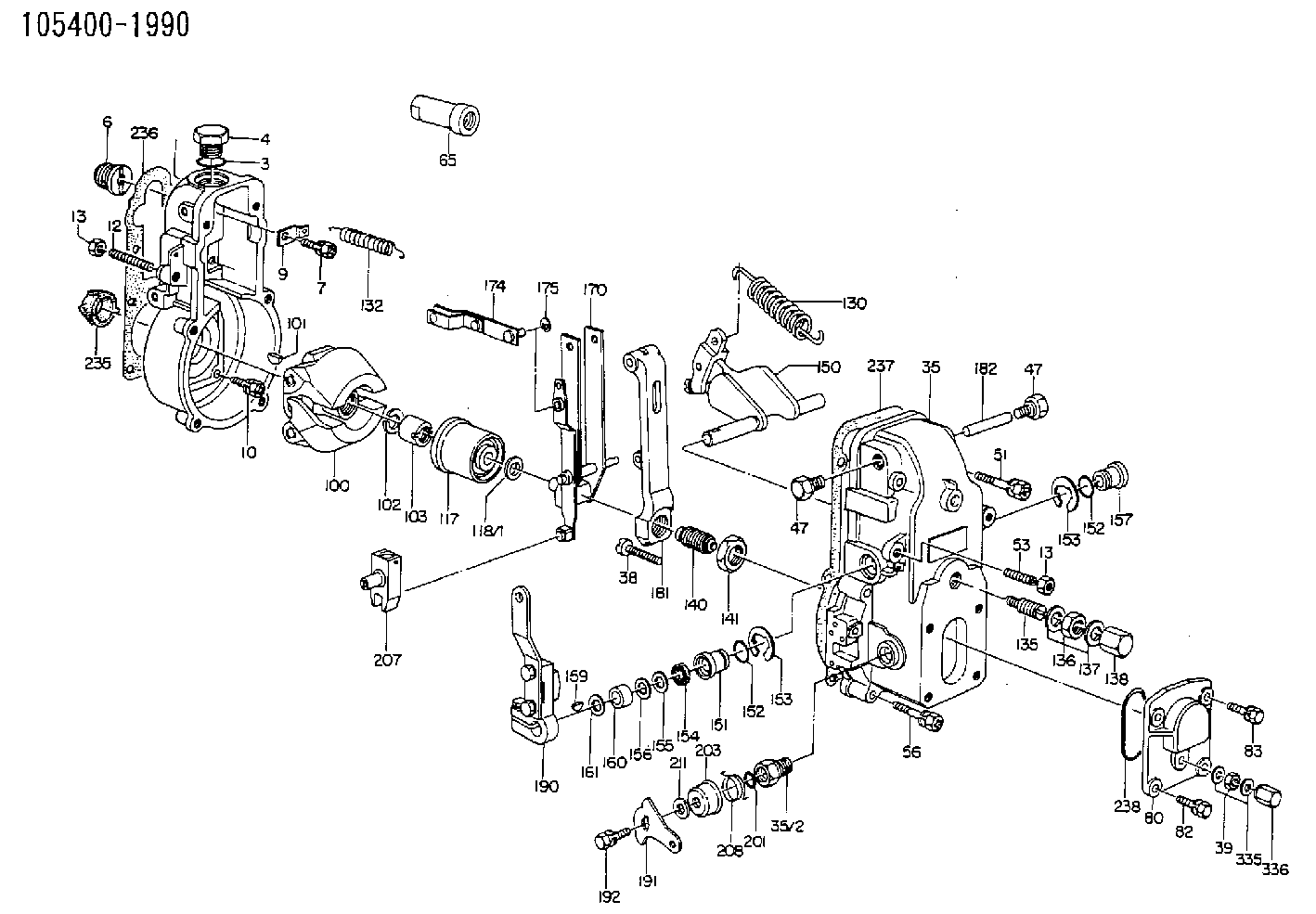
| 1. | [1] | 154000-6300 | GOVERNOR HOUSING |
| 3. | [1] | 029632-5070 | O-RING |
| 4. | [1] | 154007-2900 | CAPSULE |
| 6. | [1] | 154007-0200 | ADAPTOR |
| 7. | [1] | 020018-1840 | BLEEDER SCREW M8P1.25L18 |
| 9. | [1] | 154350-1900 | PLATE |
| 10. | [6] | 029010-6810 | BLEEDER SCREW |
| 12. | [1] | 154010-0100 | FLAT-HEAD SCREW |
| 13. | [2] | 154011-0100 | HEXAGON NUT |
| 13. | [2] | 154011-0100 | HEXAGON NUT |
| 35. | [1] | 154500-1020 | GOVERNOR COVER |
| 35/2. | [1] | 154321-0400 | BUSHING |
| 38. | [1] | 154031-2400 | FLAT-HEAD SCREW |
| 39. | [1] | 139206-0600 | UNION NUT |
| 47. | [2] | 154036-0300 | CAPSULE |
| 47. | [2] | 154036-0300 | CAPSULE |
| 51. | [2] | 020106-5040 | BLEEDER SCREW |
| 53. | [1] | 154010-1100 | FLAT-HEAD SCREW |
| 56. | [4] | 020106-3840 | BLEEDER SCREW |
| 65. | [1] | 155404-3100 | CAP |
| 80. | [1] | 154063-1400 | COVER |
| 82. | [2] | 029020-6210 | BLEEDER SCREW |
| 83. | [2] | 020006-1640 | BLEEDER SCREW M6P1L16 4T |
| 100. | [1] | 154100-3220 | FLYWEIGHT ASSEMBLY |
| 101. | [1] | 025803-1610 | WOODRUFF KEY |
| 102. | [1] | 029321-2020 | LOCKING WASHER |
| 103. | [1] | 029231-2030 | UNION NUT |
| 117. | [1] | 154123-0120 | SLIDING PIECE |
| 118/1. | [0] | 029311-0010 | SHIM D14&10.1T0.2 |
| 118/1. | [0] | 029311-0180 | SHIM D14&10.1T0.3 |
| 118/1. | [0] | 029311-0190 | SHIM D14&10.1T0.40 |
| 118/1. | [0] | 029311-0210 | SHIM D14&10.1T1 |
| 118/1. | [0] | 139410-0000 | SHIM D14.0&10.1T0.5 |
| 118/1. | [0] | 139410-0100 | SHIM D14.0&10.1T1.5 |
| 118/1. | [0] | 139410-3000 | SHIM D14&10.1T2.0 |
| 118/1. | [0] | 139410-3100 | SHIM D14&10.1T3.0 |
| 118/1. | [0] | 139410-3200 | SHIM D14&10.1T4.0 |
| 130. | [1] | 154150-2700 | GOVERNOR SPRING |
| 132. | [1] | 154154-0701 | COILED SPRING |
| 135. | [1] | 154157-1620 | HEADLESS SCREW |
| 136. | [1] | 029201-2130 | UNION NUT M12P1.0H6 |
| 137. | [2] | 026512-1540 | GASKET D15.4&12.2T1.50 |
| 138. | [1] | 154159-1200 | CAP NUT |
| 140. | [1] | 154170-6820 | HEADLESS SCREW |
| 141. | [1] | 029201-6010 | UNION NUT |
| 150. | [1] | 154200-7120 | SWIVELLING LEVER |
| 151. | [1] | 154204-3000 | BUSHING |
| 152. | [2] | 029631-8020 | O-RING |
| 152. | [2] | 029631-8020 | O-RING |
| 153. | [2] | 016010-1640 | LOCKING WASHER |
| 153. | [2] | 016010-1640 | LOCKING WASHER |
| 154. | [1] | 139611-0000 | PACKING RING |
| 155. | [1] | 139411-0000 | SHIM |
| 156. | [0] | 029311-1090 | SHIM D16&11T0.3 |
| 157. | [1] | 154204-3100 | BUSHING |
| 159. | [1] | 025803-1310 | WOODRUFF KEY |
| 160. | [1] | 154206-2800 | BUSHING |
| 161. | [0] | 154206-0200 | PLAIN WASHER D19.5&11.2T1.0 |
| 170. | [1] | 154210-0920 | FORK LEVER |
| 174. | [1] | 154230-3920 | STRAP |
| 175. | [1] | 016010-0540 | LOCKING WASHER |
| 181. | [1] | 154236-1500 | TENSIONING LEVER |
| 182. | [1] | 154237-0100 | BEARING PIN |
| 190. | [1] | 154342-2920 | CONTROL LEVER |
| 191. | [1] | 154304-1800 | CONTROL LEVER |
| 192. | [1] | 020006-1640 | BLEEDER SCREW M6P1L16 4T |
| 201. | [1] | 029631-0030 | O-RING &9.8W2.3 |
| 203. | [1] | 154322-0100 | CAP |
| 207. | [1] | 154326-5020 | CONTROL LEVER |
| 208. | [1] | 154327-7600 | COILED SPRING |
| 211/1. | [0] | 029311-0520 | SHIM D20.8&10.3T0.2 |
| 211/1. | [0] | 029311-0530 | SHIM D20.8&10.3T0.25 |
| 211/1. | [0] | 029311-0540 | SHIM D20.8&10.3T0.3 |
| 211/1. | [0] | 029311-0550 | SHIM D20.8&10.3T0.35 |
| 211/1. | [0] | 029311-0560 | SHIM D20.8&10.3T0.4 |
| 211/1. | [0] | 029311-0570 | SHIM D20.8&10.3T0.5 |
| 235. | [1] | 155412-5200 | IMPELLER WHEEL |
| 236. | [1] | 154390-0000 | GASKET |
| 237. | [1] | 154390-0300 | GASKET |
| 238. | [1] | 029635-2020 | O-RING |
| 335. | [2] | 026506-1040 | GASKET D9.9&6.2T1 |
| 336. | [1] | 154035-1600 | CAP NUT |
Include in #1:
101472-3730
as GOVERNOR
Cross reference number
Zexel num
Bosch num
Firm num
Name
105400-1990
F 019 Z1E 708
GOVERNOR
* K
* K
Information:
Before any service work is done on the fuel system, the outer surface of the injection pump housing must be clean.
1. Remove the plug from location (1). Install tool (A) in the hole with the large diameter end without the taper down. Move the governor control to the "ON" position until the rack stops against tool (A). The racks are now in center (zero) position.2. Disconnect lines (2) from the fuel injection pumps. Remove the washers. Put caps on all fuel openings. 3. Remove bushings (3) with tooling (B). 4. Install tooling (C). Hold the fuel racks in the center (zero) position and carefully remove the fuel injection pump.
When injection pumps, spacers and lifters are removed from the injection pump housing, keep the parts of each pump together so they can be installed back in their original location.
5. Remove spacers (4) from the fuel injection pump housing.
Be careful when the injection pumps are disassembled. Do not cause damage to the surface on the plunger. The plunger and barrel for each pump are made as a set. Do not put the plunger of one pump in the barrel of another pump. If one part has wear, install a complete new pump assembly. Be careful when the plunger is put into the bore of the barrel.
Do not remove gear segment (15) from plunger (10).
6. Remove plunger (10), washer (14) and spring (9) from barrel (8).7. Remove ring (12) from barrel (8) and bonnet (11).8. Remove spring (6), collar (7) and check valve assembly (13) from bonnet (11). Do not disassemble check valve assembly (13).9. Keep seal (5) with the bonnet for use at assembly.Install Fuel Injection Pumps
Make sure the fuel racks are in the center (ZERO) position before the fuel injection pumps are installed.1. Put diesel fuel on all parts to be assembled. 2. Put spring (2), collar (3) and check valve assembly (9) in position in the bonnet.
Do not slide barrel (4) against the check valve assembly when it is assembled. Scratches on the check valve can cause it to leak.
3. Put the bonnet assembly (7) and barrel (4) in position and install ring (8).4. Install spring (5), washer (10) and plunger assembly (6). 5. Put spacer (12) in position in the pump housing bore. Make sure the correct spacer is with each pump. The lobe on the cam must be at its lowest position for easy installation of the fuel injection pumps.6. Hold the fuel racks in the center (ZERO) position when the fuel pumps are installed. Put the space in gear segment (11) in alignment with the groove in barrel (4). 7. Put the injection pump straight down into the housing bore so the space in the gear segment is in alignment with pin (13) and the groove in the barrel is in alignment with dowel (14). Use tool (B) to install the pump. 8. Install seal (1) and bushing (15) in the pump housing bore. If the pump is in the correct position, bushing (15) will
Have questions with 105400-1990?
Group cross 105400-1990 ZEXEL
Nissan-Diesel
Hino
Hino
Hino
Isuzu
105400-1990
F 019 Z1E 708
GOVERNOR