Information governor
BOSCH
9 420 614 948
9420614948
ZEXEL
105400-1840
1054001840
YANMAR
12741061551
12741061551
Rating:
Scheme ###:
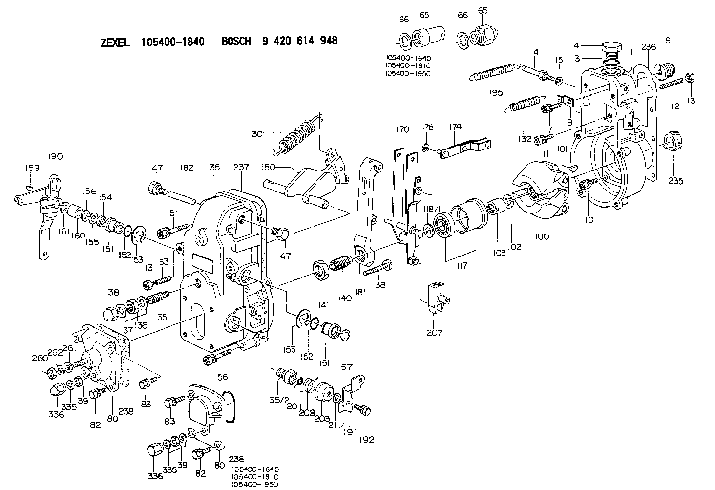
| 1. | [1] | 154000-6300 | GOVERNOR HOUSING |
| 3. | [1] | 029632-5070 | O-RING |
| 4. | [1] | 154007-2900 | CAPSULE |
| 6. | [1] | 154007-0200 | ADAPTOR |
| 7. | [1] | 020018-1840 | BLEEDER SCREW M8P1.25L18 |
| 9. | [1] | 154350-1800 | PLATE |
| 10. | [5] | 029010-6810 | BLEEDER SCREW |
| 11. | [1] | 020006-1640 | BLEEDER SCREW M6P1L16 4T |
| 12. | [1] | 154010-0100 | FLAT-HEAD SCREW |
| 13. | [2] | 154011-0100 | HEXAGON NUT |
| 13. | [2] | 154011-0100 | HEXAGON NUT |
| 14. | [1] | 154012-1720 | BLEEDER SCREW |
| 15. | [1] | 014110-8440 | LOCKING WASHER |
| 35. | [1] | 154500-3020 | GOVERNOR COVER |
| 35/2. | [1] | 154321-0400 | BUSHING |
| 38. | [1] | 154031-2400 | FLAT-HEAD SCREW |
| 39. | [1] | 139206-0600 | UNION NUT |
| 39. | [1] | 139206-0600 | UNION NUT |
| 47. | [2] | 154036-0300 | CAPSULE |
| 47. | [2] | 154036-0300 | CAPSULE |
| 51. | [2] | 020106-5040 | BLEEDER SCREW |
| 53. | [1] | 154010-0300 | FLAT-HEAD SCREW |
| 56. | [4] | 020106-3840 | BLEEDER SCREW |
| 65. | [1] | 153020-4420 | STOPPING DEVICE |
| 65. | [1] | 153020-4420 | STOPPING DEVICE |
| 66. | [1] | 026518-2240 | GASKET D21.9&18.2T1 |
| 66. | [1] | 026518-2240 | GASKET D21.9&18.2T1 |
| 80. | [1] | 154063-4520 | COVER |
| 80. | [1] | 154063-4520 | COVER |
| 82. | [2] | 029020-6210 | BLEEDER SCREW |
| 82. | [2] | 029020-6210 | BLEEDER SCREW |
| 83. | [2] | 020006-1640 | BLEEDER SCREW M6P1L16 4T |
| 83. | [2] | 020006-1640 | BLEEDER SCREW M6P1L16 4T |
| 100. | [1] | 154101-0020 | FLYWEIGHT ASSEMBLY |
| 101. | [1] | 025803-1610 | WOODRUFF KEY |
| 102. | [1] | 029321-2020 | LOCKING WASHER |
| 103. | [1] | 029231-2030 | UNION NUT |
| 117. | [1] | 154123-0120 | SLIDING PIECE |
| 118/1. | [0] | 029311-0010 | SHIM D14&10.1T0.2 |
| 118/1. | [0] | 029311-0180 | SHIM D14&10.1T0.3 |
| 118/1. | [0] | 029311-0190 | SHIM D14&10.1T0.40 |
| 118/1. | [0] | 029311-0210 | SHIM D14&10.1T1 |
| 118/1. | [0] | 139410-0000 | SHIM D14.0&10.1T0.5 |
| 118/1. | [0] | 139410-0100 | SHIM D14.0&10.1T1.5 |
| 118/1. | [0] | 139410-3000 | SHIM D14&10.1T2.0 |
| 118/1. | [0] | 139410-3100 | SHIM D14&10.1T3.0 |
| 118/1. | [0] | 139410-3200 | SHIM D14&10.1T4.0 |
| 130. | [1] | 154150-2700 | GOVERNOR SPRING |
| 132. | [1] | 154154-0701 | COILED SPRING |
| 135. | [1] | 154157-1620 | HEADLESS SCREW |
| 136. | [1] | 029201-2130 | UNION NUT M12P1.0H6 |
| 137. | [2] | 026512-1540 | GASKET D15.4&12.2T1.50 |
| 138. | [1] | 154159-1200 | CAP NUT |
| 140. | [1] | 154177-0520 | HEADLESS SCREW |
| 141. | [1] | 029201-6010 | UNION NUT |
| 150. | [1] | 154200-7120 | SWIVELLING LEVER |
| 151. | [1] | 154204-4300 | BUSHING |
| 151. | [1] | 154204-4300 | BUSHING |
| 152. | [2] | 029631-8020 | O-RING |
| 152. | [2] | 029631-8020 | O-RING |
| 153. | [2] | 016010-1640 | LOCKING WASHER |
| 153. | [2] | 016010-1640 | LOCKING WASHER |
| 154. | [1] | 139611-0000 | PACKING RING |
| 155. | [1] | 139411-0000 | SHIM |
| 156. | [0] | 029311-1070 | SHIM D16&11T0.5 |
| 157. | [1] | 154204-4400 | BUSHING |
| 159. | [1] | 025803-1310 | WOODRUFF KEY |
| 160. | [1] | 154206-2800 | BUSHING |
| 161. | [0] | 154206-0200 | PLAIN WASHER D19.5&11.2T1.0 |
| 170. | [1] | 154211-4320 | FORK LEVER |
| 174. | [1] | 154230-3920 | STRAP |
| 175. | [1] | 016010-0540 | LOCKING WASHER |
| 181. | [1] | 154236-1500 | TENSIONING LEVER |
| 182. | [1] | 154237-0100 | BEARING PIN |
| 190. | [1] | 154345-5320 | CONTROL LEVER |
| 191. | [1] | 154304-2800 | CONTROL LEVER |
| 192. | [1] | 020006-1640 | BLEEDER SCREW M6P1L16 4T |
| 195. | [1] | 154314-2600 | COILED SPRING |
| 201. | [1] | 029631-0030 | O-RING &9.8W2.3 |
| 203. | [1] | 154322-0100 | CAP |
| 207. | [1] | 154326-5120 | CONTROL LEVER |
| 208. | [1] | 154327-7300 | COILED SPRING |
| 211/1. | [0] | 029311-0520 | SHIM D20.8&10.3T0.2 |
| 211/1. | [0] | 029311-0530 | SHIM D20.8&10.3T0.25 |
| 211/1. | [0] | 029311-0540 | SHIM D20.8&10.3T0.3 |
| 211/1. | [0] | 029311-0550 | SHIM D20.8&10.3T0.35 |
| 211/1. | [0] | 029311-0560 | SHIM D20.8&10.3T0.4 |
| 211/1. | [0] | 029311-0570 | SHIM D20.8&10.3T0.5 |
| 235. | [1] | 155412-5200 | IMPELLER WHEEL |
| 236. | [1] | 154390-0000 | GASKET |
| 236. | [1] | 154390-0000 | GASKET |
| 237. | [1] | 154390-0300 | GASKET |
| 238. | [1] | 029635-2020 | O-RING |
| 260. | [1] | 013020-8040 | UNION NUT M8P1.25H7 |
| 261. | [1] | 014010-8140 | PLAIN WASHER D18&8.5T1.6 |
| 262. | [1] | 014110-8440 | LOCKING WASHER |
| 335. | [2] | 026506-1040 | GASKET D9.9&6.2T1 |
| 335. | [2] | 026506-1040 | GASKET D9.9&6.2T1 |
| 336. | [1] | 154035-1600 | CAP NUT |
| 336. | [1] | 154035-1600 | CAP NUT |
Cross reference number
Zexel num
Bosch num
Firm num
Name
105400-1840
12741061551 YANMAR
GOVERNOR
K 14JB MECHANICAL GOVERNOR GOV RSV GOV
K 14JB MECHANICAL GOVERNOR GOV RSV GOV
Information:
1. Remove the bolts and exhaust support (1) and the extension as a unit. 2. Remove extension (3) from the support.3. Remove two seal rings (2) from the extension. 4. Remove two bolts (5) from the clips.5. Remove the bolts and disconnect oil line (4) from the turbocharger. Remove the gasket. 6. Remove bolts (6) and disconnect the drain line from the turbocharger.7. Remove the gasket. 8. Remove bolts (7) that hold the manifold to the aftercooler. 9. Install tool (A) on the turbocharger and fasten a hoist.10. Remove bolts (9) that hold the turbocharger to the support bracket. Remove turbocharger (8) and the gasket. The weight of the turbocharger is 55 lb. (25 kg).11. Remove pipe (10) and the manifold from the turbocharger as a unit.Install Turbocharger
1. Install pipe (3) and the manifold as a unit on the turbocharger.2. Install tool (A) and fasten a hoist.3. Put turbocharger (1) in position and install gasket (2).4. Put 5P3931 Anti-Seize Compound on the bolts that hold the turbocharger in position. Install the bolts and tigthen them to a torque of 40 4 lb.ft. (54 5 N m). 5. Put gasket (4) in position and install the bolts. 6. Put gasket (5) and tube (6) in position and install the bolts. Put 5P3931 Anti-Seize Compound on the bolts. 7. Put gasket (7) and tube (8) in position. Put 5P3931 Anti-Seize Compound on the bolts and install them. 8. Put clips (9) and the bolts in position. 9. Put seal rings (10) in position on extension (11). Install the extension in the support. 10. Put support (12) and the extension in position. Put 5P3931 Anti-Seize Compound on the bolts. Install the bolts and tighten them to a torque of 40 4 lb.ft. (54 5 N m).
1. Install pipe (3) and the manifold as a unit on the turbocharger.2. Install tool (A) and fasten a hoist.3. Put turbocharger (1) in position and install gasket (2).4. Put 5P3931 Anti-Seize Compound on the bolts that hold the turbocharger in position. Install the bolts and tigthen them to a torque of 40 4 lb.ft. (54 5 N m). 5. Put gasket (4) in position and install the bolts. 6. Put gasket (5) and tube (6) in position and install the bolts. Put 5P3931 Anti-Seize Compound on the bolts. 7. Put gasket (7) and tube (8) in position. Put 5P3931 Anti-Seize Compound on the bolts and install them. 8. Put clips (9) and the bolts in position. 9. Put seal rings (10) in position on extension (11). Install the extension in the support. 10. Put support (12) and the extension in position. Put 5P3931 Anti-Seize Compound on the bolts. Install the bolts and tighten them to a torque of 40 4 lb.ft. (54 5 N m).