Information governor
BOSCH
F 019 Z1E 851
f019z1e851
ZEXEL
105400-1630
1054001630
YANMAR
12741061550
12741061550
Rating:
Scheme ###:
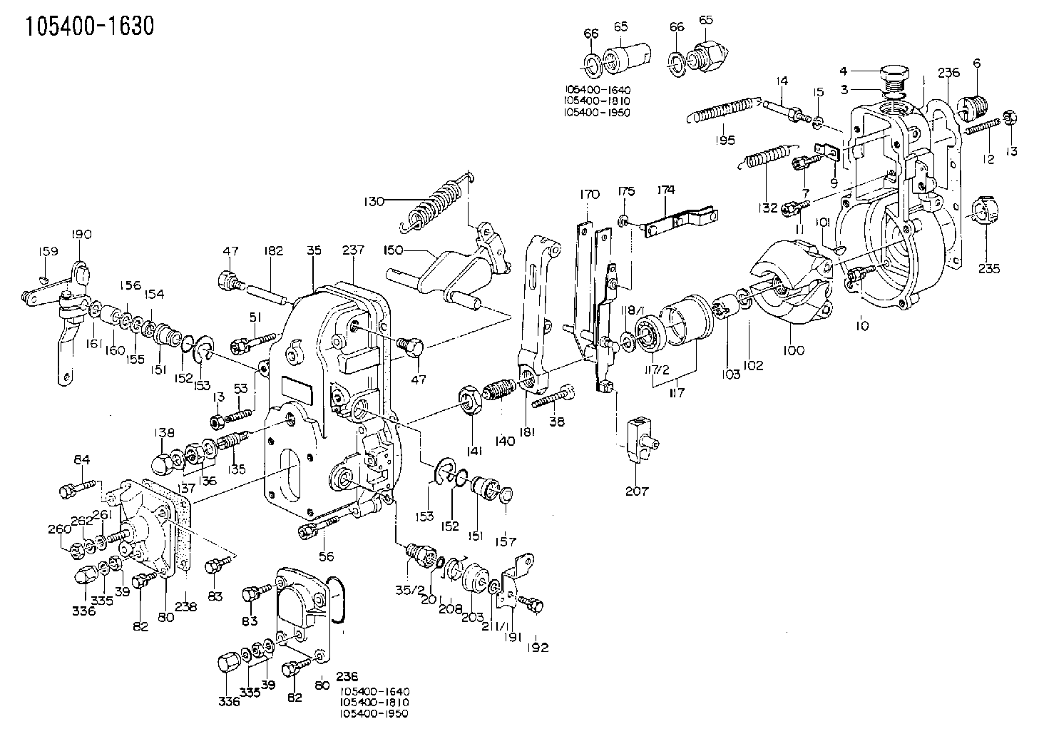
| 1. | [1] | 154000-6300 | GOVERNOR HOUSING |
| 3. | [1] | 029632-5070 | O-RING |
| 4. | [1] | 154007-2900 | CAPSULE |
| 6. | [1] | 154007-0200 | ADAPTOR |
| 7. | [1] | 020018-1840 | BLEEDER SCREW M8P1.25L18 |
| 9. | [1] | 154350-1800 | PLATE |
| 10. | [5] | 029010-6810 | BLEEDER SCREW |
| 11. | [1] | 020006-1640 | BLEEDER SCREW M6P1L16 4T |
| 12. | [1] | 154010-0100 | FLAT-HEAD SCREW |
| 13. | [2] | 154011-0100 | HEXAGON NUT |
| 13. | [2] | 154011-0100 | HEXAGON NUT |
| 14. | [1] | 154012-1720 | BLEEDER SCREW |
| 15. | [1] | 014110-8440 | LOCKING WASHER |
| 35. | [1] | 154500-3020 | GOVERNOR COVER |
| 35/2. | [1] | 154321-0400 | BUSHING |
| 38. | [1] | 154031-2400 | FLAT-HEAD SCREW |
| 39. | [1] | 139206-0600 | UNION NUT |
| 47. | [2] | 154036-0300 | CAPSULE |
| 47. | [2] | 154036-0300 | CAPSULE |
| 51. | [2] | 020106-5040 | BLEEDER SCREW |
| 53. | [1] | 154010-0100 | FLAT-HEAD SCREW |
| 56. | [4] | 020106-3840 | BLEEDER SCREW |
| 65. | [1] | 155404-5120 | STOPPING DEVICE |
| 66. | [1] | 026518-2240 | GASKET D21.9&18.2T1 |
| 80. | [1] | 154063-4520 | COVER |
| 82. | [2] | 029020-6210 | BLEEDER SCREW |
| 83. | [2] | 020006-1640 | BLEEDER SCREW M6P1L16 4T |
| 100. | [1] | 154101-0020 | FLYWEIGHT ASSEMBLY |
| 101. | [1] | 025803-1610 | WOODRUFF KEY |
| 102. | [1] | 029321-2020 | LOCKING WASHER |
| 103. | [1] | 029231-2030 | UNION NUT |
| 117. | [1] | 154123-0120 | SLIDING PIECE |
| 118/1. | [0] | 029311-0010 | SHIM D14&10.1T0.2 |
| 118/1. | [0] | 029311-0180 | SHIM D14&10.1T0.3 |
| 118/1. | [0] | 029311-0190 | SHIM D14&10.1T0.40 |
| 118/1. | [0] | 029311-0210 | SHIM D14&10.1T1 |
| 118/1. | [0] | 139410-0000 | SHIM D14.0&10.1T0.5 |
| 118/1. | [0] | 139410-0100 | SHIM D14.0&10.1T1.5 |
| 118/1. | [0] | 139410-3000 | SHIM D14&10.1T2.0 |
| 118/1. | [0] | 139410-3100 | SHIM D14&10.1T3.0 |
| 118/1. | [0] | 139410-3200 | SHIM D14&10.1T4.0 |
| 130. | [1] | 154150-4100 | GOVERNOR SPRING |
| 132. | [1] | 154154-0701 | COILED SPRING |
| 135. | [1] | 154157-1620 | HEADLESS SCREW |
| 136. | [1] | 029201-2130 | UNION NUT M12P1.0H6 |
| 137. | [2] | 026512-1540 | GASKET D15.4&12.2T1.50 |
| 138. | [1] | 154159-0100 | CAP NUT |
| 140. | [1] | 154177-0520 | HEADLESS SCREW |
| 141. | [1] | 029201-6010 | UNION NUT |
| 150. | [1] | 154200-7120 | SWIVELLING LEVER |
| 151. | [1] | 154204-4300 | BUSHING |
| 151. | [1] | 154204-4300 | BUSHING |
| 152. | [2] | 029631-8020 | O-RING |
| 152. | [2] | 029631-8020 | O-RING |
| 153. | [2] | 016010-1640 | LOCKING WASHER |
| 153. | [2] | 016010-1640 | LOCKING WASHER |
| 154. | [1] | 139611-0000 | PACKING RING |
| 155. | [1] | 139411-0000 | SHIM |
| 156. | [0] | 029311-1070 | SHIM D16&11T0.5 |
| 157. | [1] | 154204-4400 | BUSHING |
| 159. | [1] | 025803-1310 | WOODRUFF KEY |
| 160. | [1] | 154206-2800 | BUSHING |
| 161. | [0] | 154206-0200 | PLAIN WASHER D19.5&11.2T1.0 |
| 170. | [1] | 154211-4320 | FORK LEVER |
| 174. | [1] | 154230-3920 | STRAP |
| 175. | [1] | 016010-0540 | LOCKING WASHER |
| 181. | [1] | 154236-1500 | TENSIONING LEVER |
| 182. | [1] | 154237-0100 | BEARING PIN |
| 190. | [1] | 154345-5320 | CONTROL LEVER |
| 191. | [1] | 154304-2800 | CONTROL LEVER |
| 192. | [1] | 020006-1640 | BLEEDER SCREW M6P1L16 4T |
| 195. | [1] | 154314-2600 | COILED SPRING |
| 201. | [1] | 029631-0030 | O-RING &9.8W2.3 |
| 203. | [1] | 154322-0100 | CAP |
| 207. | [1] | 154326-5120 | CONTROL LEVER |
| 208. | [1] | 154327-7300 | COILED SPRING |
| 211/1. | [0] | 029311-0520 | SHIM D20.8&10.3T0.2 |
| 211/1. | [0] | 029311-0530 | SHIM D20.8&10.3T0.25 |
| 211/1. | [0] | 029311-0540 | SHIM D20.8&10.3T0.3 |
| 211/1. | [0] | 029311-0550 | SHIM D20.8&10.3T0.35 |
| 211/1. | [0] | 029311-0560 | SHIM D20.8&10.3T0.4 |
| 211/1. | [0] | 029311-0570 | SHIM D20.8&10.3T0.5 |
| 235. | [1] | 155412-5200 | IMPELLER WHEEL |
| 236. | [1] | 154390-0000 | GASKET |
| 237. | [1] | 154390-0300 | GASKET |
| 238. | [1] | 029635-2020 | O-RING |
| 260. | [1] | 013020-8040 | UNION NUT M8P1.25H7 |
| 261. | [1] | 014010-8140 | PLAIN WASHER D18&8.5T1.6 |
| 262. | [1] | 014110-8440 | LOCKING WASHER |
| 335. | [2] | 026506-1040 | GASKET D9.9&6.2T1 |
| 336. | [1] | 154035-1600 | CAP NUT |
Include in #1:
101402-9040
as GOVERNOR
Cross reference number
Zexel num
Bosch num
Firm num
Name
105400-1630
12741061550 YANMAR
GOVERNOR
K 14JB MECHANICAL GOVERNOR GOV RSV GOV
K 14JB MECHANICAL GOVERNOR GOV RSV GOV
Information:
(1) Install pin to get a dimension of ... 4.78 0.25 mm (.188 .010 in.)(2) Install dowel to get a dimension of ... 12.19 0.25 mm (.480 .010 in.)(3) Rack bearing alignment. The center of the rack bearing tab must be within 0.05 mm (.002 in.) of a vertical line that: (a) goes through the center of the rack bearing(b) is parallel to the vertical centerline of injection pump housing The following tooling is available to position the rack bearings correctly: 5P6217 Fixture and 5P6218 Driver.The correct bearing depth [19.0 0.5 mm (.75 .02 in.)] is controlled when driver is stopped by fixture.(4) Position of camshaft bearing joints (X) must be limited to area (A) ... 30 1° When viewed from the Front of the injection pump housing, all three camshaft bearings must be installed with the bearing joint (X) in an area (A) between a vertical position and a position 30° to the Right of vertical. At the same time, oil hole (Y) in the two end bearings (center bearing has no oil hole) must be to the Left of vertical.(5) Distance from bottom of housing to end of rear hollow dowel ... 1.5 0.3 mm (.06 .01 in.)(6) Maximum distance from bottom of housing to end of front hollow dowel ... 1.0 mm (.04 in.)(7) Torque for bolts ... 55 7 N m (40 5 lb.ft.)(8) Distance from rear bearing bore face to installed rear camshaft bearing ... 4.8 0.5 mm (.19 .02 in.)(9) Distance from front bearing bore face to installed front camshaft bearing ... 1.0 0.5 mm (.04 .02 in.) (10) Distance from top surface of housing to top of lower governor drive bearing ... 28.4 0.5 mm (1.12 .02 in.)(11) Install top governor drive bearing (notch end up) with sharp corner even with top surface of housing. Position center of notch so that it is in alignment with the center of oil pressure relief hole (Z) by an amount of ... 10°(12) Install dowel to get a dimension from centerline of fuel injection pump bore to dowel (seal dowel holes with aluminum ball) ... 14.76 0.10 mm (.581 .004 in.)(13) Distance from end of bearing to face of boss on housing ... 73.03 0.51 mm (2.875 .020 in.)(14) Distance between the bearings for the shaft ... 34.80 0.51 mm (1.370 .020 in.)(15) Install pins until they contact bottom of housing casting.