Information governor
BOSCH
F 019 Z4E 006
f019z4e006
ZEXEL
105400-1390
1054001390
Rating:
Scheme ###:
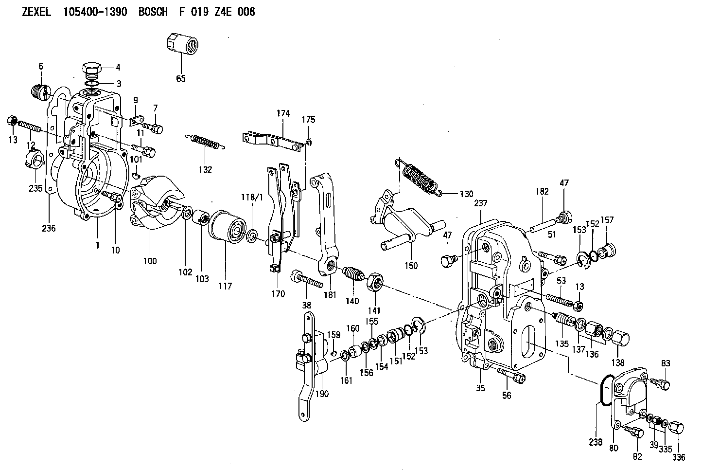
| 1. | [1] | 154000-6300 | GOVERNOR HOUSING |
| 3. | [1] | 029632-5070 | O-RING |
| 4. | [1] | 154007-2900 | CAPSULE |
| 6. | [1] | 154007-0200 | ADAPTOR |
| 7. | [1] | 020018-1840 | BLEEDER SCREW M8P1.25L18 |
| 9. | [1] | 154350-1800 | PLATE |
| 10. | [5] | 029010-6810 | BLEEDER SCREW |
| 11. | [1] | 020106-1640 | BLEEDER SCREW M6P1.0L14 |
| 12. | [1] | 154010-0100 | FLAT-HEAD SCREW |
| 13. | [2] | 154011-0100 | HEXAGON NUT |
| 13. | [2] | 154011-0100 | HEXAGON NUT |
| 35. | [1] | 154500-0020 | GOVERNOR COVER |
| 38. | [1] | 154031-2400 | FLAT-HEAD SCREW |
| 39. | [1] | 139206-0600 | UNION NUT |
| 47. | [2] | 154036-0300 | CAPSULE |
| 47. | [2] | 154036-0300 | CAPSULE |
| 51. | [2] | 020106-5040 | BLEEDER SCREW |
| 53. | [1] | 154010-0300 | FLAT-HEAD SCREW |
| 56. | [4] | 020106-3840 | BLEEDER SCREW |
| 65. | [1] | 155404-3700 | CAP |
| 80. | [1] | 154063-1400 | COVER |
| 82. | [2] | 029020-6210 | BLEEDER SCREW |
| 83. | [2] | 020006-1640 | BLEEDER SCREW M6P1L16 4T |
| 100. | [1] | 154100-4020 | FLYWEIGHT ASSEMBLY |
| 101. | [1] | 025803-1610 | WOODRUFF KEY |
| 102. | [1] | 029321-2020 | LOCKING WASHER |
| 103. | [1] | 029231-2030 | UNION NUT |
| 117. | [1] | 154123-0120 | SLIDING PIECE |
| 118/1. | [0] | 029311-0010 | SHIM D14&10.1T0.2 |
| 118/1. | [0] | 029311-0180 | SHIM D14&10.1T0.3 |
| 118/1. | [0] | 029311-0190 | SHIM D14&10.1T0.40 |
| 118/1. | [0] | 029311-0210 | SHIM D14&10.1T1 |
| 118/1. | [0] | 139410-0000 | SHIM D14.0&10.1T0.5 |
| 118/1. | [0] | 139410-0100 | SHIM D14.0&10.1T1.5 |
| 118/1. | [0] | 139410-3000 | SHIM D14&10.1T2.0 |
| 118/1. | [0] | 139410-3100 | SHIM D14&10.1T3.0 |
| 118/1. | [0] | 139410-3200 | SHIM D14&10.1T4.0 |
| 130. | [1] | 154150-0400 | GOVERNOR SPRING |
| 132. | [1] | 154154-0701 | COILED SPRING |
| 135. | [1] | 154158-1020 | HEADLESS SCREW |
| 136. | [1] | 154011-1700 | UNION NUT |
| 137. | [2] | 026512-1540 | GASKET D15.4&12.2T1.50 |
| 138. | [1] | 154159-1200 | CAP NUT |
| 140. | [1] | 154175-7620 | HEADLESS SCREW |
| 141. | [1] | 029201-6010 | UNION NUT |
| 150. | [1] | 154200-7020 | SWIVELLING LEVER |
| 151. | [1] | 154204-4300 | BUSHING |
| 152. | [2] | 029631-8020 | O-RING |
| 152. | [2] | 029631-8020 | O-RING |
| 153. | [2] | 016010-1640 | LOCKING WASHER |
| 153. | [2] | 016010-1640 | LOCKING WASHER |
| 154. | [1] | 139611-0000 | PACKING RING |
| 155. | [1] | 139411-0000 | SHIM |
| 156. | [0] | 029311-1070 | SHIM D16&11T0.5 |
| 157. | [1] | 154204-4400 | BUSHING |
| 159. | [1] | 025803-1310 | WOODRUFF KEY |
| 160. | [1] | 154206-2800 | BUSHING |
| 161. | [0] | 154206-0200 | PLAIN WASHER D19.5&11.2T1.0 |
| 170. | [1] | 154211-4320 | FORK LEVER |
| 174. | [1] | 154230-0120 | STRAP |
| 175. | [1] | 016010-0540 | LOCKING WASHER |
| 181. | [1] | 154236-4100 | TENSIONING LEVER |
| 182. | [1] | 154237-0100 | BEARING PIN |
| 190. | [1] | 154341-5120 | CONTROL LEVER |
| 235. | [1] | 155412-5200 | IMPELLER WHEEL |
| 236. | [1] | 154390-0000 | GASKET |
| 237. | [1] | 154390-0300 | GASKET |
| 238. | [1] | 029635-2020 | O-RING |
| 335. | [2] | 026506-1040 | GASKET D9.9&6.2T1 |
| 336. | [1] | 154035-1600 | CAP NUT |
| 336. | [1] | 154035-1600 | CAP NUT |
Include in #1:
101402-3481
as GOVERNOR
Cross reference number
Zexel num
Bosch num
Firm num
Name
105400-1390
F 019 Z4E 006
GOVERNOR
* K 14JB GOV RSV GOV
* K 14JB GOV RSV GOV
Information:
Table 1
Required Parts
Item Qty New Part Number Part Name Former Part Number(1)
1 1 573-8722 Coolant Tank As 469-9108
2 1 586-9617 Bracket As 491-3429
3 1 570-0813 Hose 474-9783
(1) The former part number listed is for reference only and may differ.Refer to "Replacement Procedure" for the procedure to install a new coolant tank assembly (1).Replacement Procedure
Illustration 1 g06464028
(A) Hood
Illustration 2 g06464029
(B) Tank assembly
Remove hood (A) to gain access to tank assembly (B).
Illustration 3 g06464030
(B) Tank assembly
(C) Hose
(D) Clamp
Disconnect hose (C) from tank assembly (B) by removing clamp (D).
Illustration 4 g06464533
(E) Special connector
(F) Hose assembly
(H) Clips
Illustration 5 g06464539
(G) Bolts
Disconnect special connector (E). Remove tank assembly with hose assembly (F) by removing bolts (G). Remove clips (H) and special connector (E) from hose assembly (F).
Illustration 6 g06464548
(K) Bracket
(L) Bolts
Remove bracket (K) by removing bolts (L).
Illustration 7 g06464563
(1) 573-8722 Coolant Tank As
(3) 570-0813 Hose
(E) Special connector
(H) Clips
Illustration 8 g06464617
(D1) 27 degrees
(D2) 15 mm (0.6 inch)
(D3) 10 mm (0.4 inch)
Sub-assemble new tank assembly (1), hose (3), and special connector (E) with clips (H).Note: Align hose (3) and special connector (E) at the correct angle. Refer to Illustration 7 and 8 for proper alignment.
Illustration 9 g06464631
(2) 586-9617 Bracket As
(L) Bolts
Install new bracket assembly (2) with bolts (L). Torque bolts (L) to 12 3 N m (106.2 26.6 lb in)
Illustration 10 g06464633
(1) 573-8722 Coolant Tank As
(E) Special connector
(G) Bolts
Install tank assembly (1) with bolts (G) and connect special connector (E). Tighten bolts (G) to 12 3 N m (106.2 26.6 lb in).
Illustration 11 g06464637
(1) 573-8722 Coolant Tank As
(C) Hose
(D) Clamp
Reconnect hose (C) to the tank assembly (1) with clamp (D).
Reinstall hood. Refer to Step 1.
Have questions with 105400-1390?
Group cross 105400-1390 ZEXEL
Hino
105400-1390
F 019 Z4E 006
GOVERNOR