Information governor
BOSCH
F 019 Z1E 848
f019z1e848
ZEXEL
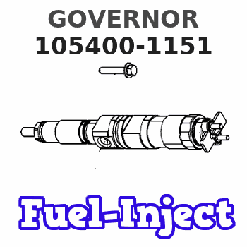
105400-1151
1054001151
Rating:
Scheme ###:
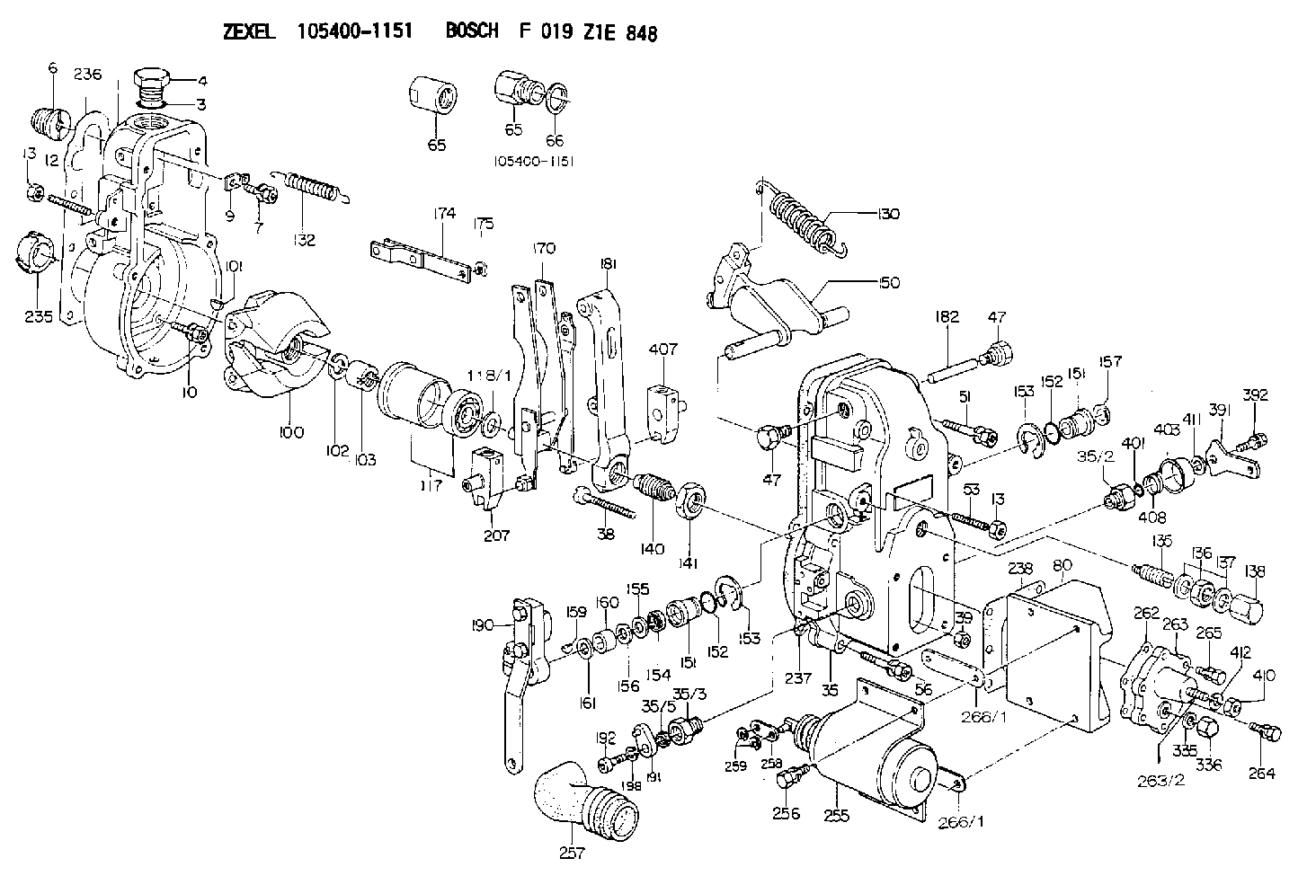
| 1. | [1] | 154000-6300 | GOVERNOR HOUSING |
| 3. | [1] | 029632-5070 | O-RING |
| 4. | [1] | 154007-2900 | CAPSULE |
| 6. | [1] | 154007-0200 | ADAPTOR |
| 7. | [1] | 020018-1840 | BLEEDER SCREW M8P1.25L18 |
| 9. | [1] | 154350-1900 | PLATE |
| 10. | [6] | 029010-6810 | BLEEDER SCREW |
| 12. | [1] | 154010-0500 | FLAT-HEAD SCREW |
| 13. | [2] | 154011-0100 | HEXAGON NUT |
| 13. | [2] | 154011-0100 | HEXAGON NUT |
| 35. | [1] | 154500-4620 | GOVERNOR COVER |
| 35/2. | [1] | 154321-0400 | BUSHING |
| 35/3. | [1] | 154321-1300 | BUSHING |
| 35/5. | [1] | 029621-0010 | PACKING RING |
| 35/10. | [2] | 015060-1480 | BEARING PIN |
| 38. | [1] | 154031-3000 | FLAT-HEAD SCREW |
| 39. | [1] | 139206-0600 | UNION NUT |
| 47. | [2] | 154036-0300 | CAPSULE |
| 47. | [2] | 154036-0300 | CAPSULE |
| 51. | [2] | 020106-5040 | BLEEDER SCREW |
| 53. | [1] | 154010-0100 | FLAT-HEAD SCREW |
| 56. | [4] | 020106-3840 | BLEEDER SCREW |
| 65. | [1] | 155404-3500 | CAP |
| 65. | [1] | 155404-3500 | CAP |
| 66. | [1] | 026518-2240 | GASKET D21.9&18.2T1 |
| 80. | [1] | 154063-1300 | COVER |
| 82. | [2] | 029020-6280 | BLEEDER SCREW |
| 83. | [2] | 020106-2840 | BLEEDER SCREW |
| 100. | [1] | 154100-6620 | FLYWEIGHT ASSEMBLY |
| 101. | [1] | 025803-1610 | WOODRUFF KEY |
| 102. | [1] | 029321-2020 | LOCKING WASHER |
| 103. | [1] | 029231-2030 | UNION NUT |
| 117. | [1] | 154123-0120 | SLIDING PIECE |
| 118/1. | [0] | 029311-0010 | SHIM D14&10.1T0.2 |
| 118/1. | [0] | 029311-0180 | SHIM D14&10.1T0.3 |
| 118/1. | [0] | 029311-0190 | SHIM D14&10.1T0.40 |
| 118/1. | [0] | 029311-0210 | SHIM D14&10.1T1 |
| 118/1. | [0] | 139410-0000 | SHIM D14.0&10.1T0.5 |
| 118/1. | [0] | 139410-0100 | SHIM D14.0&10.1T1.5 |
| 118/1. | [0] | 139410-3000 | SHIM D14&10.1T2.0 |
| 118/1. | [0] | 139410-3100 | SHIM D14&10.1T3.0 |
| 118/1. | [0] | 139410-3200 | SHIM D14&10.1T4.0 |
| 130. | [1] | 154150-0300 | GOVERNOR SPRING |
| 132. | [1] | 154154-0800 | COILED SPRING |
| 135. | [1] | 154157-0120 | HEADLESS SCREW |
| 136. | [1] | 029201-2030 | UNION NUT M12P1.0H4 |
| 137. | [2] | 026512-1540 | GASKET D15.4&12.2T1.50 |
| 138. | [1] | 154159-1200 | CAP NUT |
| 140. | [1] | 154185-1320 | HEADLESS SCREW |
| 141. | [1] | 029201-6010 | UNION NUT |
| 150. | [1] | 154200-7020 | SWIVELLING LEVER |
| 151. | [1] | 154204-4300 | BUSHING |
| 151. | [1] | 154204-4300 | BUSHING |
| 152. | [2] | 029631-8020 | O-RING |
| 152. | [2] | 029631-8020 | O-RING |
| 153. | [2] | 016010-1640 | LOCKING WASHER |
| 153. | [2] | 016010-1640 | LOCKING WASHER |
| 154. | [1] | 139611-0000 | PACKING RING |
| 155. | [1] | 139411-0000 | SHIM |
| 156. | [0] | 029311-1070 | SHIM D16&11T0.5 |
| 157. | [1] | 154204-4400 | BUSHING |
| 159. | [1] | 025803-1310 | WOODRUFF KEY |
| 160. | [1] | 154206-2800 | BUSHING |
| 161. | [0] | 154206-0200 | PLAIN WASHER D19.5&11.2T1.0 |
| 170. | [1] | 154211-7820 | FORK LEVER |
| 174. | [1] | 154230-3920 | STRAP |
| 175. | [1] | 016010-0540 | LOCKING WASHER |
| 181. | [1] | 154236-4100 | TENSIONING LEVER |
| 182. | [1] | 154237-0100 | BEARING PIN |
| 190. | [1] | 154345-4920 | CONTROL LEVER |
| 191. | [1] | 154307-9420 | CONTROL LEVER |
| 192. | [1] | 010206-1440 | HEX-SOCKET-HEAD CAP SCREW M6P1L14 |
| 198. | [1] | 029320-6010 | LOCKING WASHER |
| 203. | [1] | 154322-0100 | CAP |
| 207. | [1] | 154326-5120 | CONTROL LEVER |
| 211/1. | [0] | 029311-0520 | SHIM D20.8&10.3T0.2 |
| 211/1. | [0] | 029311-0530 | SHIM D20.8&10.3T0.25 |
| 211/1. | [0] | 029311-0540 | SHIM D20.8&10.3T0.3 |
| 211/1. | [0] | 029311-0550 | SHIM D20.8&10.3T0.35 |
| 211/1. | [0] | 029311-0560 | SHIM D20.8&10.3T0.4 |
| 211/1. | [0] | 029311-0570 | SHIM D20.8&10.3T0.5 |
| 235. | [1] | 155412-5200 | IMPELLER WHEEL |
| 236. | [1] | 154390-0000 | GASKET |
| 237. | [1] | 154390-0300 | GASKET |
| 238. | [1] | 154351-1400 | GASKET |
| 255. | [1] | 154409-9820 | SOLENOID |
| 256. | [4] | 020006-1440 | BLEEDER SCREW M6P1L14 |
| 257. | [1] | 154409-8400 | COVER |
| 258. | [1] | 154409-9000 | STRAP |
| 259. | [2] | 016010-0540 | LOCKING WASHER |
| 262. | [1] | 154353-5700 | GASKET |
| 263. | [1] | 154405-5420 | COVER |
| 263/2. | [1] | 029040-8240 | STUD |
| 264. | [1] | 029020-6260 | BLEEDER SCREW |
| 265. | [5] | 020106-2040 | BLEEDER SCREW M6P1L20 |
| 266/1. | [0] | 154351-2000 | SHIM T0.20 |
| 266/1. | [0] | 154351-2100 | SHIM T0.50 |
| 266/1. | [0] | 154351-2200 | SHIM T1.00 |
| 266/1. | [0] | 154351-2200 | SHIM T1.00 |
| 335. | [2] | 026506-1040 | GASKET D9.9&6.2T1 |
| 336. | [1] | 154035-1600 | CAP NUT |
| 391. | [1] | 154304-4720 | CONTROL LEVER |
| 392. | [1] | 020006-1640 | BLEEDER SCREW M6P1L16 4T |
| 401. | [1] | 029631-0030 | O-RING &9.8W2.3 |
| 403. | [1] | 154322-0100 | CAP |
| 407. | [1] | 154324-2820 | CONTROL LEVER |
| 408. | [1] | 154327-7300 | COILED SPRING |
| 410. | [1] | 013020-8040 | UNION NUT M8P1.25H7 |
| 411. | [1] | 014010-8140 | PLAIN WASHER D18&8.5T1.6 |
| 412. | [1] | 014110-8440 | LOCKING WASHER |
Include in #1:
101402-9010
as GOVERNOR
Cross reference number
Zexel num
Bosch num
Firm num
Name
105400-1151
GOVERNOR
K 14JB MECHANICAL GOVERNOR GOV RSV GOV
K 14JB MECHANICAL GOVERNOR GOV RSV GOV
Information:
This Program must be administered as soon as possible. When reporting the repair, use "PI3147" as the Part Number, "7751" as the Group Number, "56" as the Warranty Claim Description Code and "T" as the SIMS Description Code. Exception: If the repair is done after failure, use "PI3147" as the Part Number, "7751" as the Group Number, "96" as the Warranty Claim Description Code, and "Z" as the SIMS Description Code.
Refer to your Warranty Bulletin for detailed information with regard to Product Improvement Programs.
Completion Date
November 30, 1998Termination Date
November 30, 1998Problem
Certain 3116 and 3126 2-Valve Engines built from January 28 through February 6, 1998 with CBS heads are suspect to have improper installation of the brass injector sleeve.
Affected Product
Model & Identification Number
3116 (2WG6414-6426 5EN01269, 5EN1270, 5EN1273-1280, 5EN1282 4KG7773-7795 4KG31268NM3029-3043 9ZR771-774 )
Parts Needed
1 - 1192940 Gasket* - 1193061 Sleeve*(as required)Action Required
See the attached procedure.
Owner Notification
U.S. and Canadian owners will receive the attached Owner Notification.
Service Claim Allowances
Parts Disposition
Handle the parts in accordance with your Warranty Bulletin on warranty parts handling.
MAKE EVERY EFFORT TO COMPLETE THIS PROGRAM AS SOON AS POSSIBLE.
Attach.(1-Owner Notification)(2-Rework Procedure)Copy Of Owner Notification For U.S. And Canadian Owners
Rework Procedure
1. Check to see if the head is supplied by CBS or Gosselies. The part number is located on the front of the head on the governor side beside the lifting eye, just above the front cover. In Marine applications, it is best viewed using a light to look between the expansion tank and heat exchanger.If it is a dot-matrix, then the head is from Gosselies. If the part number is stamped, then it is from CBS.
If the head is from Gosselies (dot-matrix part number), then the engine is good and no further work is needed.
If the head is from CBS (Stamped part number) then further inspection/rework is required.
2. If the head is from CBS, remove the valve cover.3. Using a sliding caliper, align the caliper vertically using the edge of the injector spring, measure and record the distance from the timing ledge on the injector to the top face of the head for each cylinder. This measurement will be in the range of 8.39 mm but can vary from engine to engine.4. If the variation from cylinder to cylinder on the same engine is less than 0.40 mm, then the engine is good. Re-install the valve cover. No further inspection is necessary.5. If the variation from cylinder to cylinder on the same engine is greater than 0.40 mm, recheck to verify measurements, if the difference is still greater than 0.40 mm, proceed to Step 6.6. Remove all (6) injectors. Using a depth gage with flat end and a 0.75 inch diameter steel ball dropped into the sleeve, check and record the distance from the top face of the head to the top of the steel ball. This measurement should be 2.583 0.18 inches (65.61 0.46 mm).7. Remove the injector sleeve on any cylinder that the measurement from step 6 is less than 2.565 inch (65.15 mm) and