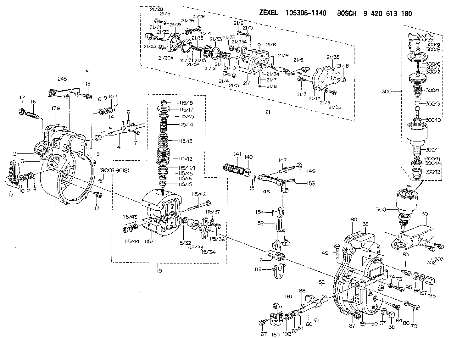
Information governor
BOSCH
9 420 613 180
9420613180
ZEXEL
105306-1140
1053061140
NISSAN-DIESEL
1910196917
1910196917

Rating:
Scheme ###:
| 1. | [1] | 153003-0320 | GOVERNOR HOUSING |
| 2. | [2] | 153005-0800 | CAPSULE |
| 3. | [2] | 153006-0100 | GASKET |
| 4. | [1] | 155004-4500 | LEVER SHAFT |
| 5. | [1] | 155005-2300 | COILED SPRING |
| 6. | [1] | 155003-1601 | CONTROL LEVER |
| 7. | [1] | 155006-0100 | BLEEDER SCREW |
| 8. | [2] | 029620-8050 | PACKING RING |
| 8. | [2] | 029620-8050 | PACKING RING |
| 9. | [0] | 029310-8040 | SHIM D13.5&8T0.2 |
| 9. | [0] | 029310-8040 | SHIM D13.5&8T0.2 |
| 9B. | [0] | 029310-8050 | SHIM D13.5&8T0.5 |
| 10. | [2] | 029300-8320 | SHIM |
| 10. | [2] | 029300-8320 | SHIM |
| 11. | [2] | 025520-1210 | SPLIT PIN |
| 11. | [2] | 025520-1210 | SPLIT PIN |
| 13. | [8] | 020106-2040 | BLEEDER SCREW M6P1L20 |
| 13. | [8] | 020106-2040 | BLEEDER SCREW M6P1L20 |
| 14. | [1] | 025802-1010 | WOODRUFF KEY |
| 15. | [1] | 153500-8020 | CONTROL LEVER |
| 16. | [1] | 155411-7100 | FLAT-HEAD SCREW |
| 17. | [1] | 155011-0200 | HEXAGON NUT |
| 21. | [1] | 154407-4723 | MANIFOLD-PRESSURE COMP. |
| 21/1. | [1] | 154408-6020 | GOVERNOR HOUSING |
| 21/1A. | [1] | 154408-2400 | SPACER BUSHING |
| 21/1B. | [1] | 134009-0000 | SPACER BUSHING |
| 21/2. | [2] | 029010-6310 | BLEEDER SCREW |
| 21/3. | [1] | 020006-1640 | BLEEDER SCREW M6P1L16 4T |
| 21/4. | [1] | 029010-6220 | BLEEDER SCREW |
| 21/5. | [5] | 014110-6440 | LOCKING WASHER |
| 21/5. | [5] | 014110-6440 | LOCKING WASHER |
| 21/5. | [5] | 014110-6440 | LOCKING WASHER |
| 21/5. | [5] | 014110-6440 | LOCKING WASHER |
| 21/6. | [1] | 154408-1400 | CONTROL LEVER |
| 21/7. | [1] | 029405-0110 | BEARING PIN |
| 21/8. | [2] | 029140-8020 | CAPSULE |
| 21/8. | [2] | 029140-8020 | CAPSULE |
| 21/9. | [1] | 154400-4620 | STOP PIN |
| 21/10. | [0] | 029312-0180 | SHIM D25.5&20T0.5 |
| 21/10B. | [0] | 029312-0210 | SHIM D25.5&20T0.2 |
| 21/11. | [1] | 154403-0200 | COILED SPRING |
| 21/12. | [1] | 029300-8260 | PLAIN WASHER |
| 21/14. | [1] | 154400-7420 | DIAPHRAGM |
| 21/15. | [1] | 029310-8560 | SHIM D14&8.4T0.7 |
| 21/16. | [1] | 139505-0000 | PLAIN WASHER |
| 21/17. | [1] | 013030-6040 | UNION NUT M6P1H3.6 |
| 21/19. | [1] | 154404-5200 | COVER |
| 21/20. | [2] | 029010-6310 | BLEEDER SCREW |
| 21/20A. | [1] | 020106-2240 | BLEEDER SCREW |
| 21/21. | [1] | 023040-6040 | UNION NUT |
| 21/22. | [1] | 154404-1100 | FLAT-HEAD SCREW |
| 21/23. | [1] | 154035-0320 | CAP NUT |
| 21/26. | [2] | 026510-1340 | GASKET D13.4&10.2T1 |
| 21/28. | [1] | 029731-0120 | EYE BOLT |
| 21/32. | [1] | 020006-1640 | BLEEDER SCREW M6P1L16 4T |
| 21/33. | [1] | 029011-0120 | BLEEDER SCREW |
| 21/33A. | [1] | 026510-1340 | GASKET D13.4&10.2T1 |
| 21/34. | [1] | 154390-0800 | GASKET |
| 21/35. | [1] | 154390-0900 | GASKET |
| 21/53. | [2] | 154413-2600 | GASKET |
| 21/54. | [1] | 139308-0700 | LOCKING WASHER |
| 35. | [1] | 153100-4110 | GOVERNOR COVER |
| 37. | [1] | 026510-1440 | GASKET D13.9&10.2T1 |
| 38. | [1] | 029111-0030 | CAPSULE |
| 49. | [1] | 153141-1700 | BLEEDER SCREW |
| 50. | [1] | 013020-6040 | UNION NUT M6P1H5 |
| 60. | [1] | 153120-0100 | LEVER SHAFT |
| 61. | [1] | 153123-0120 | CONTROL LEVER |
| 62. | [2] | 015130-2090 | TAPER PIN |
| 73. | [1] | 153141-2500 | BLEEDER SCREW |
| 74. | [1] | 013020-6040 | UNION NUT M6P1H5 |
| 79. | [1] | 029010-6310 | BLEEDER SCREW |
| 80. | [1] | 029320-6010 | LOCKING WASHER |
| 81. | [2] | 029631-1030 | O-RING |
| 82. | [2] | 029301-1080 | PLAIN WASHER D17&11.1T1 |
| 83. | [1] | 025520-2010 | SPLIT PIN |
| 84. | [1] | 153145-0100 | FLAT-HEAD SCREW |
| 87. | [5] | 020106-2840 | BLEEDER SCREW |
| 88. | [1] | 025803-1310 | WOODRUFF KEY |
| 115. | [1] | 153200-7420 | FLYWEIGHT ASSEMBLY |
| 115/1. | [1] | 153200-7910 | FLYWEIGHT |
| 115/11/1. | [2] | 153229-3800 | SLOTTED WASHER T0.5 |
| 115/11/1. | [2] | 153229-3900 | SLOTTED WASHER T0.4 |
| 115/11/1. | [2] | 153229-4000 | SLOTTED WASHER T0.3 |
| 115/11/1. | [2] | 153229-4100 | SLOTTED WASHER T0.2 |
| 115/11/1. | [2] | 153229-4600 | SLOTTED WASHER |
| 115/11/1. | [2] | 153229-4700 | SLOTTED WASHER |
| 115/11/1. | [2] | 153229-4800 | SLOTTED WASHER |
| 115/12. | [2] | 153230-9000 | GOVERNOR SPRING |
| 115/13. | [2] | 153233-7100 | GOVERNOR SPRING |
| 115/14. | [2] | 153236-0100 | GOVERNOR SPRING |
| 115/15. | [2] | 153241-0400 | UNION NUT |
| 115/16. | [2] | 153242-0100 | HEXAGON NUT |
| 115/17. | [2] | 153243-0100 | SLOTTED WASHER |
| 115/18. | [2] | 153244-0100 | UNION NUT |
| 115/32. | [1] | 029321-2020 | LOCKING WASHER |
| 115/33. | [1] | 153255-0600 | HEXAGON NUT |
| 115/34. | [1] | 153256-0300 | BUSHING |
| 115/36. | [2] | 020006-1820 | BLEEDER SCREW |
| 115/37. | [2] | 153556-2700 | PLAIN WASHER |
| 115/42. | [1] | 153270-0100 | BLEEDER SCREW |
| 115/43. | [2] | 013020-6040 | UNION NUT M6P1H5 |
| 115/44. | [1] | 153271-0100 | TAB WASHER |
| 115/45. | [0] | 029312-5120 | SHIM D33&25T0.2 |
| 115/45. | [0] | 029312-6150 | SHIM D33&26T0.5 |
| 117. | [1] | 153300-0220 | TERMINAL STUD |
| 118. | [1] | 153316-0200 | CROSS-HEAD |
| 140. | [1] | 153400-0600 | SLOTTED WASHER |
| 141. | [1] | 153401-0600 | COILED SPRING |
| 146. | [1] | 153405-3920 | STRAP |
| 147. | [1] | 153406-0700 | BLEEDER SCREW |
| 149. | [1] | 013020-5240 | UNION NUT M5P0.8H4 |
| 151. | [1] | 025520-1210 | SPLIT PIN |
| 152. | [1] | 153410-0100 | VARIABLE-FULCRUM LEVER |
| 153. | [1] | 025060-1610 | BEARING PIN |
| 154. | [1] | 025515-1510 | SPLIT PIN |
| 165. | [1] | 153500-4420 | CONTROL LEVER |
| 167. | [2] | 020006-1640 | BLEEDER SCREW M6P1L16 4T |
| 179. | [1] | 154371-5600 | GASKET |
| 180. | [1] | 154390-1200 | GASKET |
| 191. | [0] | 029311-1070 | SHIM D16&11T0.5 |
| 191B. | [0] | 029311-1090 | SHIM D16&11T0.3 |
| 192. | [0] | 154206-0200 | PLAIN WASHER D19.5&11.2T1.0 |
| 195. | [1] | 154050-1220 | HEADLESS SCREW |
| 196. | [1] | 029201-2140 | UNION NUT |
| 197. | [1] | 026512-1540 | GASKET D15.4&12.2T1.50 |
| 198. | [1] | 154159-1200 | CAP NUT |
| 248. | [1] | 153551-9220 | PLATE |
| 300. | [1] | 155423-3920 | ANEROID CAPSULE |
| 300. | [1] | 155423-3920 | ANEROID CAPSULE |
| 300/1. | [1] | 155423-3720 | DIAPHRAGM HOUSING |
| 300/2. | [1] | 155403-3021 | BELLOWS |
| 300/3. | [1] | 155423-3220 | STOP PIN |
| 300/4. | [1] | 155423-4000 | COILED SPRING |
| 300/6. | [1] | 155423-2000 | COVER |
| 300/7. | [1] | 155423-1500 | SCREW PLUG |
| 300/8. | [1] | 029240-6010 | UNION NUT M6P1.0H5* |
| 300/9. | [1] | 154035-1600 | CAP NUT |
| 300/10. | [1] | 029311-2060 | SHIM D22&12.5T0.5 |
| 300/11. | [1] | 016020-1220 | LOCKING WASHER |
| 300/12. | [1] | 155403-2200 | COVER |
| 300/14. | [1] | 139222-0000 | UNION NUT |
| 300/29. | [1] | 139805-0000 | JOINT CONNECTION |
| 300/30. | [1] | 155424-0300 | CAP |
| 301. | [1] | 153556-9520 | BRACKET |
| 302. | [2] | 020106-1640 | BLEEDER SCREW M6P1.0L14 |
| 303. | [2] | 020106-3240 | BLEEDER SCREW |
| 900S. | [1] | 025803-1310 | WOODRUFF KEY |
| 901S. | [1] | 025803-1610 | WOODRUFF KEY |
Cross reference number
Zexel num
Bosch num
Firm num
Name
Information:
2. Remove the two bolts (1) from transfer pump, and pull the pump out of accessory drive housing.3. Remove the four bolts and lock from retainer (3). Remove the retainer.4. Remove the drive gear (2). 5. Remove the two bolts, locks, and plate (5).6. Remove the variable timing unit (4) from the accessory drive housing.Install Variable Timing Unit
1. Put the variable timing unit (1) in position in the accessory drive housing.2. Install the retaining plate, locks, and two bolts.3. Install the drive gear, retainer, lock, and four bolts. Do not tighten the four bolts.4. Make an adjustment to the timing of the camshaft for the fuel injection pump. See FUEL INJECTION PUMP CAMSHAFT TIMING in TESTING AND ADJUSTING. 5. Install the cover (4) on timing gear housing.6. Put the transfer pump (3) in position on the accessory drive housing, and install the two bolts (2).7. Check to be sure all timing pins and bolts have been removed from their timing holes, and are installed in their storage positions.Disassemble Variable Timing Unit
start by: a) remove variable timing unit 1. Push down on retainer (1), and remove the pin (2).2. Remove the retainer and spring. 3. Use a hammer and punch to remove the dowels (4). Remove the two weights.4. Remove the piston and rod assembly (5) from shaft assembly (3).5. Remove the pins from nut and rod.6. Remove the rod, nut, spring, and valve from the piston assembly.Assemble Variable Timing Unit
1. Install the valve, spring, and nut on the piston assembly. Turn the nut until the distance (X) between bottom face of nut and the piston is 1.760 in. (44.7 mm). Drill a .095 .002 in. (2.41 0.05 mm) diameter hole through the nut and the threads of piston assembly. Install the pin in nut. 1. Install the rod tight against the nut. Take a measurement .156 in. (3.96 mm) from top face of nut, and put a mark at this location on rod. Drill a .095 .0.05 mm) diameter hole (1) through the rod and piston assembly at this location. Install the pin in rod.3. Install the piston and rod assembly in the shaft assembly. Install the spring, retainer, and pin in shaft assembly.4. Install the weights and dowels. Use a hammer and punch to fasten both ends of the dowels in place. Both weights must move freely after the dowels have been fastened in place.end by: a) install variable timing unit