Information governor
BOSCH
9 420 612 800
9420612800
ZEXEL
105306-1130
1053061130

Rating:
Scheme ###:
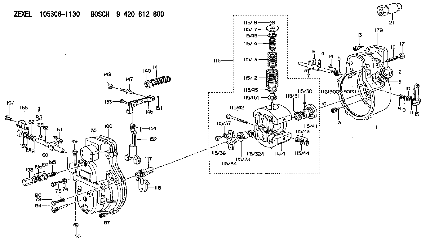
| 1. | [1] | 153003-0320 | GOVERNOR HOUSING |
| 2. | [2] | 153005-0800 | CAPSULE |
| 3. | [2] | 153006-0100 | GASKET |
| 4. | [1] | 155004-4300 | LEVER SHAFT |
| 5. | [1] | 155005-2300 | COILED SPRING |
| 6. | [1] | 155003-1601 | CONTROL LEVER |
| 7. | [1] | 155006-0700 | BLEEDER SCREW |
| 8. | [2] | 029620-8050 | PACKING RING |
| 9. | [0] | 029310-8040 | SHIM D13.5&8T0.2 |
| 9B. | [0] | 029310-8050 | SHIM D13.5&8T0.5 |
| 10. | [2] | 029300-8320 | SHIM |
| 11. | [2] | 025520-1210 | SPLIT PIN |
| 13. | [8] | 020106-2040 | BLEEDER SCREW M6P1L20 |
| 13. | [8] | 020106-2040 | BLEEDER SCREW M6P1L20 |
| 14. | [1] | 025802-1010 | WOODRUFF KEY |
| 15. | [1] | 155400-9820 | CONTROL LEVER |
| 16. | [1] | 155411-7100 | FLAT-HEAD SCREW |
| 17. | [1] | 155011-0200 | HEXAGON NUT |
| 21. | [1] | 134510-8420 | CONNECTOR |
| 35. | [1] | 153100-7020 | GOVERNOR COVER |
| 49. | [1] | 153141-1700 | BLEEDER SCREW |
| 50. | [1] | 013020-6040 | UNION NUT M6P1H5 |
| 60. | [1] | 153120-0100 | LEVER SHAFT |
| 61. | [1] | 153123-0120 | CONTROL LEVER |
| 62. | [2] | 015130-2090 | TAPER PIN |
| 73. | [1] | 153141-1500 | BLEEDER SCREW |
| 74. | [1] | 029240-6010 | UNION NUT M6P1.0H5* |
| 79. | [1] | 029010-6310 | BLEEDER SCREW |
| 80. | [1] | 029320-6010 | LOCKING WASHER |
| 81. | [2] | 029631-1030 | O-RING |
| 82. | [2] | 029301-1080 | PLAIN WASHER D17&11.1T1 |
| 83. | [1] | 025520-2010 | SPLIT PIN |
| 84. | [1] | 153145-0100 | FLAT-HEAD SCREW |
| 87. | [5] | 020106-2840 | BLEEDER SCREW |
| 88. | [1] | 025803-1310 | WOODRUFF KEY |
| 115. | [1] | 153209-1720 | FLYWEIGHT ASSEMBLY |
| 115/1. | [1] | 153200-0010 | FLYWEIGHT |
| 115/11/1. | [2] | 153228-0100 | SLOTTED WASHER T0.1 |
| 115/11/1. | [2] | 153228-0200 | SLOTTED WASHER T0.2 |
| 115/11/1. | [2] | 153228-0300 | SLOTTED WASHER T0.3 |
| 115/11/1. | [2] | 153228-0400 | SLOTTED WASHER T0.4 |
| 115/12. | [2] | 153230-6300 | GOVERNOR SPRING |
| 115/13. | [2] | 153233-9200 | GOVERNOR SPRING |
| 115/14. | [2] | 153236-6901 | GOVERNOR SPRING |
| 115/17. | [2] | 153243-0100 | SLOTTED WASHER |
| 115/18. | [2] | 153244-0100 | UNION NUT |
| 115/30. | [2] | 156011-0100 | FELT |
| 115/31. | [4] | 153251-0300 | DAMPER |
| 115/32/1. | [2] | 153254-0100 | SHIM D17.9&12.5T2.0 |
| 115/32/1. | [2] | 153254-0200 | SHIM D17.9&12.5T1.9 |
| 115/32/1. | [2] | 153254-0300 | SHIM D17.9&12.5T1.8 |
| 115/32/1. | [2] | 153254-0400 | SHIM D17.9&12.5T1.7 |
| 115/32/1. | [2] | 153254-0500 | SHIM D17.9&12.5T1.75 |
| 115/32/1. | [2] | 153254-0600 | SHIM D17.9&12.5T1.85 |
| 115/33. | [1] | 153255-0100 | HEXAGON NUT |
| 115/34. | [1] | 153256-0300 | BUSHING |
| 115/36. | [2] | 020006-1820 | BLEEDER SCREW |
| 115/37. | [2] | 153556-2700 | PLAIN WASHER |
| 115/41. | [1] | 153260-0120 | BUSHING |
| 115/42. | [1] | 153270-0100 | BLEEDER SCREW |
| 115/43. | [2] | 029220-6010 | UNION NUT |
| 115/44. | [1] | 153271-0100 | TAB WASHER |
| 115/45. | [0] | 029312-5120 | SHIM D33&25T0.2 |
| 115/45. | [0] | 029312-5120 | SHIM D33&25T0.2 |
| 115/45. | [0] | 029312-6150 | SHIM D33&26T0.5 |
| 116. | [1] | 025803-1310 | WOODRUFF KEY |
| 117. | [1] | 153300-0220 | TERMINAL STUD |
| 118. | [1] | 153316-0200 | CROSS-HEAD |
| 140. | [1] | 153400-0600 | SLOTTED WASHER |
| 141. | [1] | 153401-0600 | COILED SPRING |
| 146. | [1] | 153405-3920 | STRAP |
| 147. | [1] | 153406-0700 | BLEEDER SCREW |
| 149. | [1] | 013020-5240 | UNION NUT M5P0.8H4 |
| 151. | [1] | 025520-1210 | SPLIT PIN |
| 152. | [1] | 153410-0100 | VARIABLE-FULCRUM LEVER |
| 153. | [1] | 025060-1610 | BEARING PIN |
| 154. | [1] | 025515-1510 | SPLIT PIN |
| 165. | [1] | 153500-5920 | CONTROL LEVER |
| 167. | [2] | 020006-1640 | BLEEDER SCREW M6P1L16 4T |
| 179. | [1] | 154371-5600 | GASKET |
| 180. | [1] | 154390-1200 | GASKET |
| 191. | [0] | 029311-1070 | SHIM D16&11T0.5 |
| 191B. | [0] | 029311-1090 | SHIM D16&11T0.3 |
| 192. | [0] | 154206-0200 | PLAIN WASHER D19.5&11.2T1.0 |
| 195. | [1] | 154050-3620 | HEADLESS SCREW |
| 196. | [1] | 029201-2290 | UNION NUT |
| 197. | [2] | 026512-1540 | GASKET D15.4&12.2T1.50 |
| 198. | [1] | 154159-1200 | CAP NUT |
| 900S. | [1] | 025803-1310 | WOODRUFF KEY |
| 901S. | [1] | 025803-1610 | WOODRUFF KEY |
Include in #1:
106671-4600
as GOVERNOR
Cross reference number
Zexel num
Bosch num
Firm num
Name
Information:
1. Disconnect the fuel outlet line (1) and fuel inlet line (3) from the priming pump.2. Disconnect the fuel line (2) from pump.3. Remove the bolts (4) from pump.4. Remove the fuel transfer pump.5. Remove the fuel lines (1) and (3) from pump.Install Fuel Transfer Pump
1. Install the two fuel lines in transfer pump.2. Put the fuel transfer pump in position in the accessory drive housing, and install the two bolts.3. Connect the two fuel lines to priming pump.4. Connect the fuel line to transfer pump.Disassemble Fuel Transfer Pump
start by: a) remove fuel transfer pump 1. Remove the nut (2), gear (3), and key.2. Remove the cage (1). Remove the O-ring seals from the cage.3. Use tool setup (A) to remove the bearing and seals from cage (1).4. Remove the cover (4).
Be careful during disassembly and assembly of pump to prevent damage to the contacting surfaces of the cover (4) and the pump body.
5. Remove the bolt (5), spring, and ball for the check valve for the priming pump. 6. Remove the gear (7), and gear and shaft assembly (6) from pump body. 7. Use tool setup (A) to remove the bearing from the pump body.Assemble Fuel Transfer Pump
1. Clean all parts thoroughly before assembling the pump. 2. Use tool setup (A) to install the bearing in the pump body.3. Put the gear, and gear and shaft assembly in position in pump body.4. Put a thin amount of 8S6747 Liquid Gasket Material on the face of body assembly that is against the cover.
Do not let the liquid gasket material get into the pump.
5. Put the cover into position on pump body and install the bolts. The gear and shaft assembly must turn freely after the bolts in cover have been tightened.6. Install the check valve ball, spring, and bolt for the priming pump in the cover. 7. Use tool setup (B) to install the seals in cage. Install the two seals with the lips of seals toward each other.8. Use tool setup (A) to install the bearing in cage assembly. Install the O-ring seals on cage. 9. Put clean oil on O-ring seals and lips of seals. 10. Put the cage assembly in position, and install the woodruff key, gear, and nut. Tighten nut to 22 5 lb.ft. (3.0 0.7 mkg).end by: a) install fuel transfer pump