Information governor
BOSCH
F 019 Z1E 558
f019z1e558
ZEXEL
105306-0992
1053060992
NISSAN-DIESEL
1910197508
1910197508
Rating:
Scheme ###:
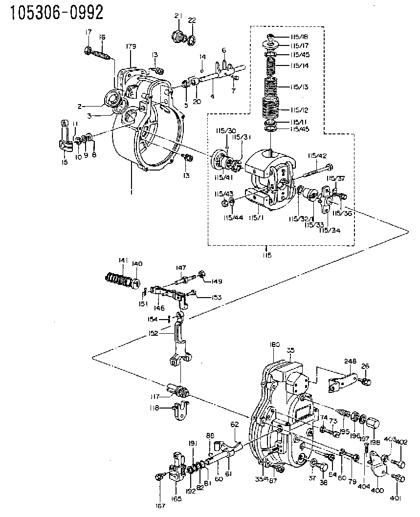
| 1. | [1] | 153003-1220 | GOVERNOR HOUSING |
| 2. | [2] | 153005-0800 | CAPSULE |
| 3. | [2] | 153006-0100 | GASKET |
| 4. | [1] | 155004-2901 | LEVER SHAFT |
| 5. | [1] | 155005-2600 | COILED SPRING |
| 6. | [1] | 155003-1601 | CONTROL LEVER |
| 7. | [1] | 155006-0100 | BLEEDER SCREW |
| 8. | [1] | 029620-8050 | PACKING RING |
| 9. | [0] | 029310-8040 | SHIM D13.5&8T0.2 |
| 9B. | [0] | 029310-8050 | SHIM D13.5&8T0.5 |
| 10. | [1] | 029300-8320 | SHIM |
| 11. | [1] | 025520-1210 | SPLIT PIN |
| 13. | [8] | 020106-2040 | BLEEDER SCREW M6P1L20 |
| 13. | [8] | 020106-2040 | BLEEDER SCREW M6P1L20 |
| 14. | [1] | 025802-1010 | WOODRUFF KEY |
| 15. | [1] | 155414-1320 | CONTROL LEVER |
| 16. | [1] | 155411-7100 | FLAT-HEAD SCREW |
| 17. | [1] | 155011-0200 | HEXAGON NUT |
| 20. | [1] | 155618-3200 | BUSHING |
| 21. | [1] | 155404-1700 | CAP |
| 22. | [1] | 026524-3040 | GASKET |
| 26. | [2] | 029010-6810 | BLEEDER SCREW |
| 35. | [1] | 153100-6520 | GOVERNOR COVER |
| 35/4. | [2] | 029040-5010 | STUD |
| 37. | [1] | 026510-1440 | GASKET D13.9&10.2T1 |
| 38. | [1] | 029111-0030 | CAPSULE |
| 60. | [1] | 153120-2600 | LEVER SHAFT |
| 61. | [1] | 153123-0120 | CONTROL LEVER |
| 62. | [2] | 015130-2090 | TAPER PIN |
| 73. | [1] | 153141-2400 | BLEEDER SCREW |
| 74. | [1] | 013020-6040 | UNION NUT M6P1H5 |
| 79. | [1] | 029010-6310 | BLEEDER SCREW |
| 80. | [1] | 029320-6010 | LOCKING WASHER |
| 81. | [1] | 029631-1030 | O-RING |
| 82. | [1] | 029301-1080 | PLAIN WASHER D17&11.1T1 |
| 84. | [1] | 153145-0100 | FLAT-HEAD SCREW |
| 87. | [5] | 020106-2840 | BLEEDER SCREW |
| 88. | [1] | 025803-1310 | WOODRUFF KEY |
| 115. | [1] | 153209-0921 | FLYWEIGHT ASSEMBLY |
| 115/1. | [1] | 153200-9410 | FLYWEIGHT |
| 115/11. | [2] | 153228-2300 | SLOTTED WASHER |
| 115/11B. | [2] | 153228-2500 | SLOTTED WASHER |
| 115/11C. | [2] | 153228-2600 | SLOTTED WASHER |
| 115/11D. | [2] | 153228-2700 | SLOTTED WASHER |
| 115/11E. | [2] | 153228-3500 | SLOTTED WASHER |
| 115/11F. | [2] | 153228-3600 | SLOTTED WASHER |
| 115/11G. | [2] | 153228-3700 | SLOTTED WASHER |
| 115/12. | [2] | 153231-2800 | GOVERNOR SPRING |
| 115/13. | [2] | 153233-9100 | GOVERNOR SPRING |
| 115/14. | [2] | 153236-5500 | GOVERNOR SPRING |
| 115/17. | [2] | 153243-1300 | SLOTTED WASHER |
| 115/18. | [2] | 153244-0200 | UNION NUT |
| 115/30. | [2] | 156011-0100 | FELT |
| 115/31. | [4] | 153251-0900 | DAMPER |
| 115/32/1. | [2] | 153254-0100 | SHIM D17.9&12.5T2.0 |
| 115/32/1. | [2] | 153254-0200 | SHIM D17.9&12.5T1.9 |
| 115/32/1. | [2] | 153254-0300 | SHIM D17.9&12.5T1.8 |
| 115/32/1. | [2] | 153254-0400 | SHIM D17.9&12.5T1.7 |
| 115/32/1. | [2] | 153254-0500 | SHIM D17.9&12.5T1.75 |
| 115/32/1. | [2] | 153254-0600 | SHIM D17.9&12.5T1.85 |
| 115/33. | [1] | 153255-0100 | HEXAGON NUT |
| 115/34. | [1] | 153256-0300 | BUSHING |
| 115/36. | [2] | 020006-1820 | BLEEDER SCREW |
| 115/37. | [2] | 153556-2700 | PLAIN WASHER |
| 115/41. | [1] | 153260-0420 | BUSHING |
| 115/42. | [1] | 153270-0100 | BLEEDER SCREW |
| 115/43. | [1] | 013020-6040 | UNION NUT M6P1H5 |
| 115/44. | [1] | 153271-0100 | TAB WASHER |
| 115/45. | [0] | 029312-5120 | SHIM D33&25T0.2 |
| 115/45. | [0] | 029312-5120 | SHIM D33&25T0.2 |
| 115/45. | [0] | 029312-6150 | SHIM D33&26T0.5 |
| 117. | [1] | 153300-0220 | TERMINAL STUD |
| 118. | [1] | 153316-0200 | CROSS-HEAD |
| 140. | [1] | 153400-0600 | SLOTTED WASHER |
| 141. | [1] | 153401-0800 | COILED SPRING |
| 146. | [1] | 153405-3920 | STRAP |
| 147. | [1] | 153406-0700 | BLEEDER SCREW |
| 149. | [1] | 013020-5240 | UNION NUT M5P0.8H4 |
| 151. | [1] | 025520-1210 | SPLIT PIN |
| 152. | [1] | 153410-0100 | VARIABLE-FULCRUM LEVER |
| 153. | [1] | 025060-1610 | BEARING PIN |
| 154. | [1] | 025515-1510 | SPLIT PIN |
| 165. | [1] | 153500-7120 | CONTROL LEVER |
| 167. | [2] | 020006-1640 | BLEEDER SCREW M6P1L16 4T |
| 179. | [1] | 154371-5600 | GASKET |
| 180. | [1] | 154390-1200 | GASKET |
| 191. | [0] | 029311-1070 | SHIM D16&11T0.5 |
| 191B. | [0] | 029311-1090 | SHIM D16&11T0.3 |
| 192. | [0] | 154206-0200 | PLAIN WASHER D19.5&11.2T1.0 |
| 195. | [1] | 154050-1220 | HEADLESS SCREW |
| 196. | [1] | 029201-2030 | UNION NUT M12P1.0H4 |
| 197. | [1] | 026512-1540 | GASKET D15.4&12.2T1.50 |
| 198. | [1] | 154159-1200 | CAP NUT |
| 248. | [1] | 153556-4600 | PLATE |
| 400. | [1] | 153556-4320 | BRACKET |
| 401. | [1] | 020006-1240 | BLEEDER SCREW M6P1L12 4T |
| 402. | [1] | 155615-1600 | BLEEDER SCREW |
| 403. | [1] | 013020-6040 | UNION NUT M6P1H5 |
| 404. | [1] | 010706-1440 | FLAT-HEAD SCREW M6P1L14 |
| 900S. | [1] | 025803-1310 | WOODRUFF KEY |
| 901S. | [1] | 025803-1610 | WOODRUFF KEY |
Cross reference number
Zexel num
Bosch num
Firm num
Name
105306-0992
1910197508 NISSAN-DIESEL
GOVERNOR
K 14JA MECHANICAL GOVERNOR GOV RQ GOV
K 14JA MECHANICAL GOVERNOR GOV RQ GOV
Information:
If there has been a previous repair, part age/hours will apply. Retain a copy of the previous repair invoice in the dealer's records for audit purposes, and specify repair date and machine hours in the "Additional Comments" section of the warranty claim.
Dealer to perform most economical repair.
Description____________________________SMCS Code___Hours
Wash___________________________________1091-074 ___0.2
Inner fender __________________________7252-010 ___0.2
R&I DPF _______________________________108F-010 ___1.2
program ECM - program DPF serial # ,
ASH reset, factory passwords __________1901-591 ___0.2
Test after Repair _____________________108F-030 ___0.2
This letter is to be performed during a recommended ash service as stated in Media number SEBU8087. Ash cleaning is a part of the recommended maintenance of the engine, customer is responsible for the labor required to remove and install the DPF.
PARTS DISPOSITION
Handle the parts in accordance with your Warranty Bulletin on warranty parts handling.
Rework Procedure
1. Wash debris from Diesel Particulate Filter (DPF) as necessary.
Image1.1.1
2. Remove the Fender (A): Loosen and remove the nuts and bolts from the fender of the truck. Retain the fender and fasteners for reuse. Refer to Image 1.1.1.
Image1.2.1
3. Remove the Step (B): Loosen and remove fasteners from the step of the truck. Retain the step and fasteners for reuse. Refer to Image 1.2.1.
Image1.3.1
Image1.3.2
4. Remove the Pipe Clamps: Loosen and remove clamps from the Inlet Pipe (C)& Outlet Pipe (D) of the DPF?s. Refer to Image 1.3.1 & Image 1.3.2
Image1.4.1
5. Remove tubes (E) and sensor box mounting bolts (F) to unplug sensor box connection. Refer to Image 1.4.1.
Image1.5.1
6. Remove DPF mounting bolts: Loosen and remove fasteners from the mounting of the DPF. Retain the mounting and fasteners for reuse. No jack will be used to hold DPF, DPF is supported by air tank brackets. Properly support DPF until it rests on the bracket. Refer to Image 1.5.1.
Image1.6.1
7. Slide the DPF forward and remove. Remove the CGI pipe (G) after the DPF has been removed. Refer to Image 1.6.1.
Image 1.7.1 shows the chassis after the welded DPF has been removed.
Image1.7.1
Image1.7.2
8. Install the Clamped DPF with mounting bolts (reuse the bolts). Install the new 330-4036 CGI Pipe for Group 1 & Group 2 with the 304-3048 Clamp. Check Inlet, Outlet and CGI pipes alignment, mounting brackets should be aligned with OEM brackets.
Refer OEM guidelines for connecting Inlet & CGI connections.
Image 1.7.2 shows the clamped DPF after it has been installed in the chassis.
9. Install the step and fender that were removed in Step 2 and Step 3.
10. Reset the engine ash model. Refer Media Number RENR9705.
11. Start the engine and use CAT ET to ensure that the status parameter Diesel Particulate Trap #1 Differential Pressure has a value greater than zero. Also ensure status parameters Diesel Particulate Trap #1 Intake Temperature, and Diesel Particulate Trap #1 Outlet Temperature show reasonable values and increase with the rising exhaust temperatures.