Information governor
BOSCH
9 420 610 118
9420610118
ZEXEL
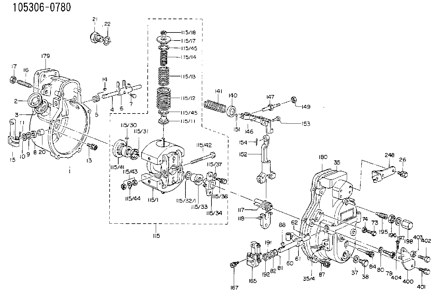
105306-0780
1053060780
NISSAN-DIESEL
1910197502
1910197502

Rating:
Scheme ###:
| 1. | [1] | 153003-1220 | GOVERNOR HOUSING |
| 2. | [2] | 153005-0800 | CAPSULE |
| 3. | [2] | 153006-0100 | GASKET |
| 4. | [1] | 155004-2901 | LEVER SHAFT |
| 5. | [1] | 155005-2600 | COILED SPRING |
| 6. | [1] | 155003-1601 | CONTROL LEVER |
| 7. | [1] | 155006-0100 | BLEEDER SCREW |
| 8. | [1] | 029620-8050 | PACKING RING |
| 9. | [0] | 029310-8040 | SHIM D13.5&8T0.2 |
| 9B. | [0] | 029310-8050 | SHIM D13.5&8T0.5 |
| 10. | [1] | 029300-8320 | SHIM |
| 11. | [1] | 025520-1210 | SPLIT PIN |
| 13. | [8] | 020106-2040 | BLEEDER SCREW M6P1L20 |
| 14. | [1] | 025802-1010 | WOODRUFF KEY |
| 15. | [1] | 155414-1320 | CONTROL LEVER |
| 16. | [1] | 155411-7100 | FLAT-HEAD SCREW |
| 17. | [1] | 155011-0200 | HEXAGON NUT |
| 20. | [1] | 155618-3200 | BUSHING |
| 21. | [1] | 155404-1700 | CAP |
| 22. | [1] | 026524-3040 | GASKET |
| 26. | [2] | 029010-6810 | BLEEDER SCREW |
| 35. | [1] | 153100-6520 | GOVERNOR COVER |
| 35/4. | [2] | 029040-5010 | STUD |
| 37. | [1] | 026510-1440 | GASKET D13.9&10.2T1 |
| 38. | [1] | 029111-0030 | CAPSULE |
| 60. | [1] | 153120-2600 | LEVER SHAFT |
| 61. | [1] | 153123-0120 | CONTROL LEVER |
| 62. | [2] | 015130-2090 | TAPER PIN |
| 73. | [1] | 153141-1300 | BLEEDER SCREW |
| 74. | [1] | 029240-6010 | UNION NUT M6P1.0H5* |
| 79. | [1] | 029010-6310 | BLEEDER SCREW |
| 80. | [1] | 029320-6010 | LOCKING WASHER |
| 81. | [1] | 029631-1030 | O-RING |
| 82. | [1] | 029301-1080 | PLAIN WASHER D17&11.1T1 |
| 84. | [1] | 153145-0100 | FLAT-HEAD SCREW |
| 87. | [5] | 020106-2840 | BLEEDER SCREW |
| 88. | [1] | 025803-1310 | WOODRUFF KEY |
| 115. | [1] | 153209-0320 | FLYWEIGHT ASSEMBLY |
| 115/1. | [1] | 153200-9410 | FLYWEIGHT |
| 115/11. | [2] | 153228-1800 | SLOTTED WASHER T0.10 |
| 115/11B. | [2] | 153228-1900 | SLOTTED WASHER T0.20 |
| 115/11C. | [2] | 153228-2000 | SLOTTED WASHER T0.30 |
| 115/11D. | [2] | 153228-2100 | SLOTTED WASHER T0.40 |
| 115/11E. | [2] | 153228-3200 | SLOTTED WASHER |
| 115/11F. | [2] | 153228-3300 | SLOTTED WASHER |
| 115/11G. | [2] | 153228-3400 | SLOTTED WASHER |
| 115/12. | [2] | 153231-2100 | GOVERNOR SPRING |
| 115/13. | [2] | 153233-9100 | GOVERNOR SPRING |
| 115/14. | [2] | 153236-9700 | GOVERNOR SPRING |
| 115/17. | [2] | 153243-1300 | SLOTTED WASHER |
| 115/18. | [2] | 153244-0200 | UNION NUT |
| 115/30. | [2] | 156011-0100 | FELT |
| 115/31. | [4] | 153251-0900 | DAMPER |
| 115/32/1. | [2] | 153254-0100 | SHIM D17.9&12.5T2.0 |
| 115/32/1. | [2] | 153254-0200 | SHIM D17.9&12.5T1.9 |
| 115/32/1. | [2] | 153254-0300 | SHIM D17.9&12.5T1.8 |
| 115/32/1. | [2] | 153254-0400 | SHIM D17.9&12.5T1.7 |
| 115/32/1. | [2] | 153254-0500 | SHIM D17.9&12.5T1.75 |
| 115/32/1. | [2] | 153254-0600 | SHIM D17.9&12.5T1.85 |
| 115/33. | [1] | 153255-0100 | HEXAGON NUT |
| 115/34. | [1] | 153256-0300 | BUSHING |
| 115/36. | [2] | 020006-1820 | BLEEDER SCREW |
| 115/37. | [2] | 153556-2700 | PLAIN WASHER |
| 115/41. | [1] | 153260-0420 | BUSHING |
| 115/42. | [1] | 153270-0100 | BLEEDER SCREW |
| 115/43. | [1] | 013020-6040 | UNION NUT M6P1H5 |
| 115/44. | [1] | 153271-0100 | TAB WASHER |
| 115/45. | [0] | 029312-5120 | SHIM D33&25T0.2 |
| 115/45. | [0] | 029312-5120 | SHIM D33&25T0.2 |
| 115/45. | [0] | 029312-6150 | SHIM D33&26T0.5 |
| 117. | [1] | 153300-0220 | TERMINAL STUD |
| 118. | [1] | 153316-0200 | CROSS-HEAD |
| 140. | [1] | 153400-0600 | SLOTTED WASHER |
| 141. | [1] | 153401-0800 | COILED SPRING |
| 146. | [1] | 153405-3920 | STRAP |
| 147. | [1] | 153406-0700 | BLEEDER SCREW |
| 149. | [1] | 013020-5220 | UNION NUT M5P0.8H4 |
| 151. | [1] | 025520-1210 | SPLIT PIN |
| 152. | [1] | 153410-0100 | VARIABLE-FULCRUM LEVER |
| 153. | [1] | 025060-1610 | BEARING PIN |
| 154. | [1] | 025515-1510 | SPLIT PIN |
| 165. | [1] | 153500-7120 | CONTROL LEVER |
| 167. | [2] | 020006-1640 | BLEEDER SCREW M6P1L16 4T |
| 179. | [1] | 154371-5600 | GASKET |
| 180. | [1] | 154390-1200 | GASKET |
| 191. | [0] | 029311-1070 | SHIM D16&11T0.5 |
| 191B. | [0] | 029311-1090 | SHIM D16&11T0.3 |
| 192. | [0] | 154206-0200 | PLAIN WASHER D19.5&11.2T1.0 |
| 195. | [1] | 154050-3820 | HEADLESS SCREW |
| 196. | [1] | 029201-2030 | UNION NUT M12P1.0H4 |
| 197. | [1] | 026512-1540 | GASKET D15.4&12.2T1.50 |
| 198. | [1] | 154159-1200 | CAP NUT |
| 248. | [1] | 153556-4600 | PLATE |
| 400. | [1] | 153556-4320 | BRACKET |
| 401. | [1] | 020006-1240 | BLEEDER SCREW M6P1L12 4T |
| 402. | [1] | 155615-1600 | BLEEDER SCREW |
| 403. | [1] | 013020-6040 | UNION NUT M6P1H5 |
| 404. | [1] | 010706-1440 | FLAT-HEAD SCREW M6P1L14 |
| 900S. | [1] | 025803-1310 | WOODRUFF KEY |
| 901S. | [1] | 025803-1610 | WOODRUFF KEY |
Cross reference number
Zexel num
Bosch num
Firm num
Name
Information:
Image1.1.1
5. Attach a hose to the other end of the fuel rail and hold the free end of the hose in a cup/bucket of water. Hose shown is a JIC 37o ?6 hose. Refer to Illustration 1.2.1
Image1.2.1
6. Pressurize the cooling system with compressed air and regulate pressure between 5-15 psi.
Do Not Exceed 15 psi or Cooling System Damage Can Result.
7. Submerse the hose in a cup/bucket of water.
8. Monitor for 10 minutes and check for a steady rate of air bubbles coming out of the hose that is submersed in the cup/bucket of water.
9. If steady stream of air is present, replace the cylinder head, coolant regulators, and both 030-7937 port connectors. Depending on the application, you will need to replace some cooling system seals. (List of seals by application to be included)
10. Once the cylinder heads have been replaced pressure test the head again using the same procedure. Once this has been completed the cooling system should be flushed using instructions listed below.
Cleaning the Cooling System
1. Drain all of the coolant form cooling system.
2. Fill the cooling system with clean water.
3. Start engine and run it until the thermostat opens.
4. Add two cups of non-foaming liquid automatic dish washer soap.
Note: Do not use plain dish soap. Aeration of the cooling system and resultant damage could occur.
5. After the soap has bee added run engine for approximately twenty minutes. Check to see if the fuel is breaking up.
6. If the fuel is still not breaking up than add two more cups of soap and run for 10 minutes. Drain mixture from cooling system.
7. Fill cooling system with clean water and check surface for fuel. If fuel is present, repeat steps 3 through 7. When water is clear, drain and rinse the cooling system one more time. Then add coolant and conditioner.