Information gasket
BOSCH
9 411 611 852
9411611852
ZEXEL
139514-0300
1395140300
ISUZU
8973864210
8973864210
Rating:
Include in ###:
Number on scheme 133

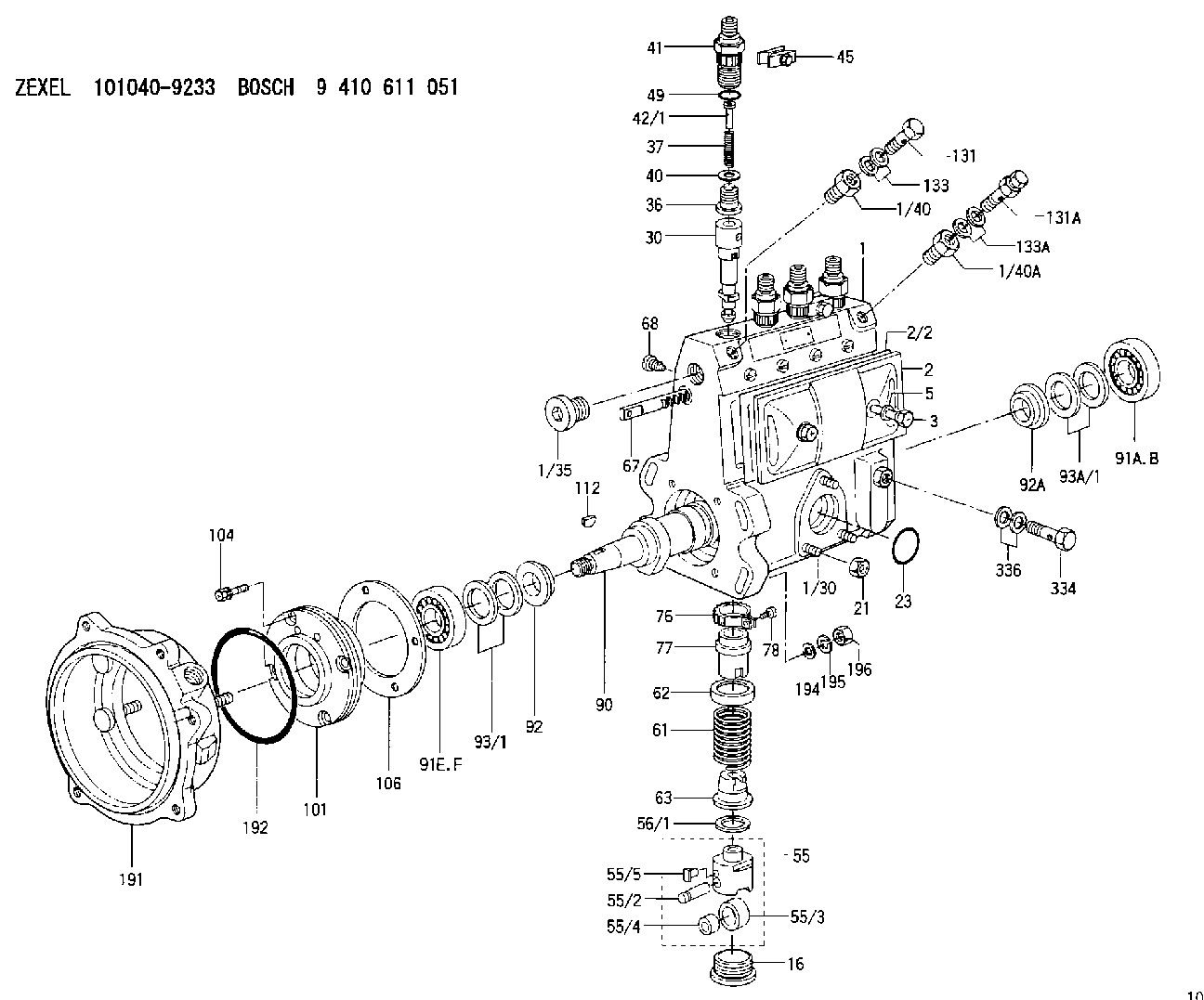
1010409233
as GASKET
1010419530
as GASKET
D18.6&14.2T1.6
1010419550
as GASKET
1010605440
as GASKET
D18.6&14.2T1.6
1010605470
as GASKET
1010605501
as GASKET
D18.6&14.2T1.6
1010605570
as GASKET
Cross reference number
Zexel num
Bosch num
Firm num
Name
139514-0300
9 411 611 852
8973864210 ISUZU
GASKET
C 90HY GASKET Standard parts Others
C 90HY GASKET Standard parts Others
139514-0300
9 411 611 852
228432640A HINO
GASKET
C 90HY GASKET Standard parts Others
C 90HY GASKET Standard parts Others
139514-0300
9 411 611 852
S228432640 HINO
GASKET
A C 90HY GASKET Standard parts Others
A C 90HY GASKET Standard parts Others
139514-0300
9 411 611 852
S228432640A HINO
GASKET
B C 90HY GASKET Standard parts Others
B C 90HY GASKET Standard parts Others
Information:
Dismantling And Installing The Camshaft (as from 3 cylinder engine)
Fasten engine in rotatable engine stand.Dismantling
4-561. Remove the rocker chamber covers and the rocker brackets. Take out the push-rods. Remove cooling blower, crankcase breather tube, oil pan and oil suction pipe with strainer.Fig. 4-56
4-572. Remove V-belt pulley and front cover. (Retainer for V-belt pulley No. 143400)Fig. 4-57 The V-belt pulley bolt has left-hand thread.
4-583. Remove oil pipe with oil pump. Take off idler gear with hub.Fig. 4-58
4-594. Pull out camshaft.Fig. 4-59Installing
1. Position the gearwheels with the marks lines up and carefully insert the camshaft with gear. Note that the marking on the injection pump gear differs, depending on the number of engine cylinder (3 cylinders, or 4, 5, 6 cylinders.)
4-60a) F3L: The reference mark on the injection pump gearwheel of this model is a figure 3 with a dot above it. Fig. 4-60
4-61b) F4/5/6L: Engines of these types have a dot to mark the mating point of the injection pump gearwheel.Fig. 4-61 Pay attention to modified marks on camshaft and injection pump gears.2. Fit a new rubber O-seal on the discharge pipe of the oil pump.3. Position the oil pump and pipe on the crankcase and tighten the oil pump screws. Adjust the gear flank clearance to the value stated in the specifications. The manufacturing material and tightening torque for the bolts fastening the lube oil pump have been changed.
4-624. Tighten and lock down the stud securing the idler gear mounting (on the oil delivery pipe clip), in accordance with the instructions for tightening bolts and studs.Fig. 4-62
4-635. Fit oil suction pipe with strainer.Fig. 4-63
4-646. Place compression spring and cap on camshaft spigot.Fig. 4-64
4-657. Fit a new gasket to the front cover, strick it in position with grease and mount the cover.Fig. 4-65
4-668. Grease the lip of the radial packing ring in the front cover and the contact surface of the vee-belt pulley. Install the vee-belt pulley, having brought the locating pin in the crankshaft gearwheel.Fig. 4-66
4-679. Screw in bolt (left-hand thread), preload and tighten as per instructions. (Retainer for V-belt pulley No. 143400, gauge No. 101910).Fig. 4-6710. Apply grease to a new gasket and stick it in position on the sump. Assemble the sump. Tightening torque for the oil drain plugs illustrated is: 150 Nm
4-6811. Fasten retainer for crankcase breather pipe at oil pan.Fig. 4-6812. Assemble the push-rods.
4-6913. Mount the rocker brackets. Tighten nuts as quoted in Specification Data.Fig. 4-69
4-7014. Adjust the valve clearance.Fig. 4-7015. Stick new gasket with sealing compound to rocker chamber cover. Position cover, align and fit bolt with new washer. Tightening see Specification Data.
4-7116. Align blower to holes and attach to front-end cover.Fig. 4-7117. Push idler pulley upward and install belt.18. Hook in the air cowling at the top and close at the bottom.Checking And Gauging The Crankshaft
1. Inspect crankshaft for cracks (by magnaflux method).2. Remove the gearwheel from the crankshaft.3. Support crankshaft at outer main journals on prism-shaped blocks.
4-724. Determine the hardness of the journal surfaces with a scleroscope. Conversions of the redlings
Have questions with 139514-0300?
Group cross 139514-0300 ZEXEL
Isuzu
139514-0300
9 411 611 852
8973864210
GASKET
Hino
139514-0300
9 411 611 852
228432640A
GASKET
139514-0300
9 411 611 852
S228432640
GASKET
139514-0300
9 411 611 852
S228432640A
GASKET