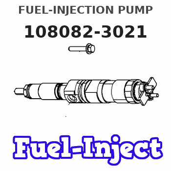
Information fuel-injection pump
BOSCH
9 410 612 045
9410612045
ZEXEL
108082-3021
1080823021
HINO
221004092A
221004092a
Rating:
Scheme ###:
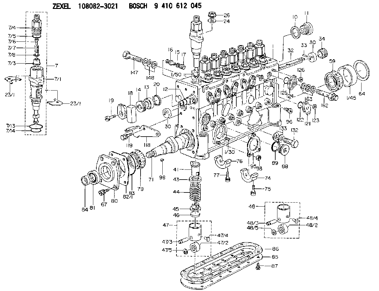
| 1. | [1] | 134082-0420 | PUMP HOUSING |
| 1/30. | [3] | 029040-6020 | STUD |
| 1/45. | [1] | 134311-0000 | SPACER RING |
| 1/50. | [16] | 134138-0200 | STUD |
| 7. | [8] | 134148-1420 | PLUNGER-AND-BARREL ASSY |
| 7/1. | [1] | 134178-0920 | PLUNGER-AND-BARREL ASSY |
| 7/3. | [1] | 134160-4120 | DELIVERY-VALVE ASSEMBLY |
| 7/4. | [1] | 134171-0320 | FITTING |
| 7/5. | [1] | 016500-1800 | O-RING |
| 7/6. | [1] | 134117-1700 | FILLER PIECE |
| 7/7. | [1] | 134112-2200 | COILED SPRING |
| 7/8. | [1] | 134115-0300 | GASKET |
| 7/13. | [1] | 139727-0200 | O-RING |
| 7/14. | [1] | 139723-0000 | O-RING |
| 10. | [1] | 026516-2040 | GASKET D19.9&16.2T1 |
| 11. | [1] | 134227-1200 | CAPSULE |
| 12. | [1] | 134227-2400 | CONTROL ROD |
| 13. | [1] | 134227-1400 | BEARING PLATE |
| 14. | [1] | 134227-0300 | BUSHING |
| 15. | [8] | 014160-6110 | CONICAL SPRING WASHER |
| 16. | [8] | 134227-0400 | BEARING PIN |
| 17. | [8] | 134227-0501 | FLAT-HEAD SCREW |
| 18. | [1] | 134227-3400 | CONNECTOR |
| 19. | [1] | 139005-0300 | HEX-SOCKET-HEAD CAP SCREW |
| 20. | [1] | 139320-0000 | PLAIN WASHER |
| 23/1. | [0] | 139400-0900 | SHIM T0.500 |
| 23/1. | [0] | 139400-1000 | SHIM T0.525 |
| 23/1. | [0] | 139400-1100 | SHIM T0.550 |
| 23/1. | [0] | 139400-1200 | SHIM T0.575 |
| 23/1. | [0] | 139400-1300 | SHIM T0.600 |
| 23/1. | [0] | 139400-1400 | SHIM T0.625 |
| 23/1. | [0] | 139400-1500 | SHIM T0.650 |
| 23/1. | [0] | 139400-1600 | SHIM T0.675 |
| 23/1. | [0] | 139400-1700 | SHIM T0.700 |
| 23/1. | [0] | 139400-1800 | SHIM T0.725 |
| 23/1. | [0] | 139400-1900 | SHIM T0.750 |
| 23/1. | [0] | 139400-2000 | SHIM T0.775 |
| 23/1. | [0] | 139400-2100 | SHIM T0.800 |
| 23/1. | [0] | 139400-2200 | SHIM T0.825 |
| 23/1. | [0] | 139400-2300 | SHIM T0.850 |
| 23/1. | [0] | 139400-2400 | SHIM T0.875 |
| 23/1. | [0] | 139400-2500 | SHIM T0.900 |
| 23/1. | [0] | 139400-2600 | SHIM T0.925 |
| 23/1. | [0] | 139400-2700 | SHIM T0.950 |
| 23/1. | [0] | 139400-2700 | SHIM T0.950 |
| 23/1. | [0] | 139400-2800 | SHIM T0.975 |
| 23/1. | [0] | 139400-2900 | SHIM T1.000 |
| 23/1. | [0] | 139400-3000 | SHIM T1.025 |
| 23/1. | [0] | 139400-3100 | SHIM T1.050 |
| 23/1. | [0] | 139400-3200 | SHIM T1.075 |
| 23/1. | [0] | 139400-3300 | SHIM T1.100 |
| 23/1. | [0] | 139400-3400 | SHIM T1.125 |
| 23/1. | [0] | 139400-3500 | SHIM T1.150 |
| 23/1. | [0] | 139400-3600 | SHIM T1.175 |
| 23/1. | [0] | 139400-3700 | SHIM T1.200 |
| 23/1. | [0] | 139400-3800 | SHIM T1.225 |
| 23/1. | [0] | 139400-3900 | SHIM T1.250 |
| 23/1. | [0] | 139400-4000 | SHIM T1.275 |
| 23/1. | [0] | 139400-4100 | SHIM T1.300 |
| 23/1. | [0] | 139400-4200 | SHIM T1.325 |
| 23/1. | [0] | 139400-4300 | SHIM T1.350 |
| 23/1. | [0] | 139400-4400 | SHIM T1.375 |
| 23/1. | [0] | 139400-4500 | SHIM T1.400 |
| 23/1. | [0] | 139400-4600 | SHIM T1.425 |
| 23/1. | [0] | 139400-4700 | SHIM T1.450 |
| 23/1. | [0] | 139400-4800 | SHIM T1.475 |
| 23/1. | [0] | 139400-4900 | SHIM T1.500 |
| 23/1. | [0] | 139400-5000 | SHIM T1.525 |
| 23/1. | [0] | 139400-5100 | SHIM T1.550 |
| 23/1. | [0] | 139400-5200 | SHIM T1.575 |
| 23/1. | [0] | 139400-5300 | SHIM T1.600 |
| 23/1. | [0] | 139400-5400 | SHIM T1.625 |
| 23/1. | [0] | 139400-5500 | SHIM T1.650 |
| 23/1. | [0] | 139400-5600 | SHIM T1.675 |
| 23/1. | [0] | 139400-5700 | SHIM T1.700 |
| 23/1. | [0] | 139400-5800 | SHIM T1.725 |
| 23/1. | [0] | 139400-5900 | SHIM T1.750 |
| 23/1. | [0] | 139400-6000 | SHIM T1.775 |
| 23/1. | [0] | 139400-6100 | SHIM T1.800 |
| 23/1. | [0] | 139400-6200 | SHIM T1.825 |
| 23/1. | [0] | 139400-6300 | SHIM T1.850 |
| 23/1. | [0] | 139400-6400 | SHIM T1.875 |
| 23/1. | [0] | 139400-6500 | SHIM T1.900 |
| 23/1. | [0] | 139400-6600 | SHIM T1.925 |
| 23/1. | [0] | 139400-6700 | SHIM T1.950 |
| 23/1. | [0] | 139400-6800 | SHIM T1.975 |
| 24. | [16] | 134132-0300 | PLAIN WASHER D20&11T2.5 |
| 26. | [16] | 139210-0200 | UNION NUT |
| 30. | [2] | 134001-0000 | BUSHING |
| 30. | [2] | 134001-0000 | BUSHING |
| 32. | [1] | 134258-1720 | CONTROL RACK |
| 33. | [1] | 024030-2030 | BEARING PIN |
| 34. | [1] | 134222-0000 | BUSHING |
| 41. | [8] | 134241-0720 | CONTROL SLEEVE |
| 43. | [8] | 134216-0401 | SLOTTED WASHER |
| 44. | [8] | 134215-1300 | COMPRESSION SPRING |
| 45. | [8] | 134217-0800 | SLOTTED WASHER |
| 46. | [8] | 134563-2800 | SPRING SEAT |
| 47. | [4] | 134200-1320 | TAPPET |
| 47/2. | [1] | 134204-0300 | ROLLER |
| 47/3. | [1] | 134203-0200 | BEARING PIN |
| 47/4. | [1] | 131206-0500 | SLIDER |
| 47/5. | [1] | 134208-0100 | LOCKING WASHER |
| 48. | [4] | 134200-1220 | TAPPET |
| 48/2. | [1] | 134204-0300 | ROLLER |
| 48/3. | [1] | 134203-0200 | BEARING PIN |
| 48/4. | [1] | 131206-0500 | SLIDER |
| 48/5. | [1] | 134208-0100 | LOCKING WASHER |
| 59. | [1] | 016650-2230 | BEARING PLATE |
| 64. | [1] | 134303-0500 | SHIM D59.8&43T1.6 |
| 67. | [4] | 139006-4200 | BLEEDER SCREW |
| 71. | [1] | 134387-0200 | CAMSHAFT |
| 74. | [1] | 134306-1300 | BEARING SHELL |
| 75. | [2] | 020106-2040 | BLEEDER SCREW M6P1L20 |
| 76. | [2] | 134306-1400 | BEARING SHELL |
| 77. | [4] | 020106-2040 | BLEEDER SCREW M6P1L20 |
| 79. | [1] | 035302-0600 | BEARING PLATE |
| 80. | [1] | 134316-3300 | COVER |
| 81. | [1] | 139634-0200 | PACKING RING |
| 82/1. | [0] | 134314-0700 | SHIM T0.1 |
| 82/1. | [0] | 134314-0800 | SHIM T0.12 |
| 82/1. | [0] | 134314-0900 | SHIM T0.14 |
| 82/1. | [0] | 134314-1000 | SHIM T0.16 |
| 82/1. | [0] | 134314-1100 | SHIM T0.18 |
| 82/1. | [0] | 134314-1200 | SHIM T0.3 |
| 82/1. | [0] | 134314-1300 | SHIM T0.5 |
| 83. | [1] | 139766-0000 | O-RING |
| 84. | [1] | 134563-2500 | SLIDING PIECE |
| 85. | [1] | 134043-0700 | COVER |
| 86. | [1] | 134042-1500 | GASKET |
| 87. | [14] | 134563-2900 | FLAT-HEAD SCREW |
| 88. | [1] | 134045-0100 | CAPSULE |
| 89. | [1] | 026524-2940 | GASKET D28.9&24.3T2 |
| 93. | [3] | 139206-0400 | UNION NUT |
| 95. | [1] | 131041-0800 | GASKET |
| 96. | [8] | 134047-0000 | CAPSULE |
| 98. | [1] | 025806-2210 | WOODRUFF KEY |
| 118. | [1] | 134496-5800 | POINTER |
| 119. | [2] | 029020-6210 | BLEEDER SCREW |
| 121. | [7] | 134227-1800 | CAPSULE |
| 122. | [7] | 139720-0000 | O-RING |
| 123. | [14] | 139206-0400 | UNION NUT |
| 124. | [1] | 134227-2700 | CAPSULE |
| 125. | [1] | 139720-0000 | O-RING |
| 126. | [2] | 139206-0400 | UNION NUT |
| 132. | [1] | 134430-3820 | EYE BOLT |
| 133. | [2] | 139516-0200 | GASKET |
| 147. | [1] | 139810-0700 | EYE BOLT |
| 148. | [3] | 139510-0300 | GASKET |
| 162. | [1] | 134424-0820 | OVER FLOW VALVE |
| 163. | [3] | 139514-0300 | GASKET |
Cross reference number
Zexel num
Bosch num
Firm num
Name
Information:
Illustration 7 g06347860
Injector male spade terminals
There are two options to build injector adapter harness for C3.3.If available, use the injector connector removed from C3.3 harness. Cut both 100 mm wires from the connector and attach bullet terminals that fit in the injector adapter harness C3.8 terminal from injector test kit.If no harness is available, build a harness with the following. Two female spade terminals for injector male spade terminal, two 16 gauge 100 mm wires, and two bullet terminals for injector adapter harness C3.8 terminal.
Illustration 8 g06345429
Injector adapter harness C2.4
Illustration 9 g06346223
Injector adapter harness C3.8
Illustration 10 g06346237
Injector male spade terminals
There are two options to build injector adapter harness for C2.4.If available, use the injector connector removed from C2.4 harness. Cut both 100 mm wires from the connector and attach bullet terminals that fit in the injector adapter harness C3.8 terminal from injector test kit.If no harness is available, build a harness with the following. Two female spade terminals for injector male spade terminal, two 16 gauge 100 mm wires, and two bullet terminals for injector adapter harness C3.8 terminal.Injector Test Set-up
Illustration 11 g06346391
Mounted nozzle test group
Find a suitable stable and surface to either mount or place the nozzle test group. Fill fuel container with #1 diesel and install high-pressure hose assembly. Use adaptors, if needed, based on nozzle tester. Tighten the fuel line adapter to (25 ft lbs). Install the fuel line adapter and tighten to (25 ft lbs) to allow connection to the injector.
Illustration 12 g06346423
Injector holder assembly
Take the injector test kit and remove all parts to assemble, as shown above. Take the injector holder and the clear fuel shield with screws from the kit and remove the screws using a 3mm alan wrench. Assemble the parts so the clear fuel shield with screws is on the bottom. While, the mounted injector holder is on top with the screws removed from before.
Illustration 13 g06346719
Fuel collector and injector holder
Place injector holder onto a fuel collector or another container to capture the injection spray.
Illustration 14 g06346839
Injector setup and harness connection
Install the injector that is needing to be tested into the opening at the top of injector holder. Attach the return fuel drain hose and run the drain hose to another fuel collector. Make the harness connection using the correct adapter for the C2.4, C3.3, and C3.8 engines. Connect the injector pulse tool and the injector adapter harness to the injector.
Illustration 15 g06346868
Complete setup of nozzle tester and injector test kit
Once injector test kit and nozzle test group are set up, connect fuel line adaptor on the high-pressure hose assembly to the injector, leave connection loose. Actuate the lever on the nozzle test group until fuel drips from connection allowing air to purge from setup. Tighten fuel line adaptor at injector to (25 ft lbs).Injector Test Procedure
Illustration 16 g06346881
Mounted nozzle test group (close-up)
Inspect the injector for any leaks. Using the lever on the nozzle tester group, build injection fuel pressure to (5000 psi). Turn the locking valve to insure there is no leakage back through the tester.
Let the nozzle test