Information fuel-injection pump
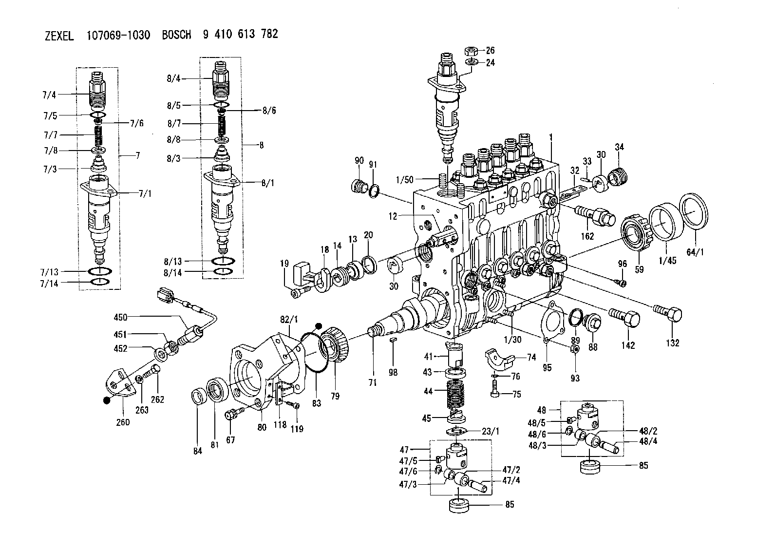
BOSCH
9 410 613 782
9410613782
ZEXEL
107069-1030
1070691030
NISSAN-DIESEL
16703Z5761
16703z5761
Rating:
Scheme ###:
| 1. | [1] | 135000-0320 | PUMP HOUSING |
| 1/30. | [3] | 029040-6020 | STUD |
| 1/45. | [1] | 134311-0000 | SPACER RING |
| 1/50. | [12] | 135024-0000 | STUD |
| 7. | [5] | 135130-0220 | PLUNGER-AND-BARREL ASSY |
| 7/1. | [5] | 135176-0320 | PLUNGER-AND-BARREL ASSY M4 |
| 7/3. | [5] | 135182-0020 | VALVE MM2 |
| 7/4. | [5] | 135116-0000 | FITTING |
| 7/5. | [5] | 029632-0030 | O-RING |
| 7/6. | [5] | 134117-2000 | FILLER PIECE |
| 7/7. | [5] | 134112-2800 | COILED SPRING |
| 7/8. | [5] | 135115-0000 | GASKET |
| 7/13. | [5] | 135134-0000 | O-RING |
| 7/14. | [5] | 135134-0200 | O-RING |
| 8. | [1] | 135130-0620 | PLUNGER-AND-BARREL ASSY |
| 8/1. | [1] | 135176-0520 | PLUNGER-AND-BARREL ASSY M6 |
| 8/3. | [1] | 135182-0020 | VALVE MM2 |
| 8/4. | [1] | 135116-0000 | FITTING |
| 8/5. | [1] | 029632-0030 | O-RING |
| 8/6. | [1] | 134117-2000 | FILLER PIECE |
| 8/7. | [1] | 134112-2800 | COILED SPRING |
| 8/8. | [1] | 135115-0000 | GASKET |
| 8/13. | [1] | 135134-0000 | O-RING |
| 8/14. | [1] | 135134-0200 | O-RING |
| 12. | [1] | 135227-0020 | CONTROL ROD |
| 13. | [1] | 134227-1400 | BEARING PLATE |
| 14. | [1] | 134227-0300 | BUSHING |
| 18. | [1] | 135227-1000 | CONNECTOR |
| 19. | [1] | 139005-0300 | HEX-SOCKET-HEAD CAP SCREW |
| 20. | [1] | 139320-0000 | PLAIN WASHER |
| 23/1. | [0] | 139415-0000 | SHIM D19&10T0.500 |
| 23/1. | [0] | 139415-0100 | SHIM D19&10T0.525 |
| 23/1. | [0] | 139415-0200 | SHIM D19&10T0.550 |
| 23/1. | [0] | 139415-0300 | SHIM D19&10T0.575 |
| 23/1. | [0] | 139415-0400 | SHIM D19&10T0.600 |
| 23/1. | [0] | 139415-0500 | SHIM D19&10T0.625 |
| 23/1. | [0] | 139415-0600 | SHIM D19&10T0.650 |
| 23/1. | [0] | 139415-0700 | SHIM D19&10T0.675 |
| 23/1. | [0] | 139415-0800 | SHIM D19&10T0.700 |
| 23/1. | [0] | 139415-0900 | SHIM D19&10T0.725 |
| 23/1. | [0] | 139415-1000 | SHIM D19&10T0.750 |
| 23/1. | [0] | 139415-1100 | SHIM D19&10T0.775 |
| 23/1. | [0] | 139415-1200 | SHIM D19&10T0.800 |
| 23/1. | [0] | 139415-1300 | SHIM D19&10T0.825 |
| 23/1. | [0] | 139415-1400 | SHIM D19&10T0.850 |
| 23/1. | [0] | 139415-1500 | SHIM D19&10T0.875 |
| 23/1. | [0] | 139415-1600 | SHIM D19&10T0.900 |
| 23/1. | [0] | 139415-1700 | SHIM D19&10T0.925 |
| 23/1. | [0] | 139415-1800 | SHIM D19&10T0.950 |
| 23/1. | [0] | 139415-1900 | SHIM D19&10T0.975 |
| 23/1. | [0] | 139415-2000 | SHIM D19&10T1.000 |
| 23/1. | [0] | 139415-2100 | SHIM D19&10T1.025 |
| 23/1. | [0] | 139415-2200 | SHIM D19&10T1.050 |
| 23/1. | [0] | 139415-2300 | SHIM D19&10T1.075 |
| 23/1. | [0] | 139415-2400 | SHIM D19&10T1.100 |
| 23/1. | [0] | 139415-2500 | SHIM D19&10T1.125 |
| 23/1. | [0] | 139415-2600 | SHIM D19&10T1.150 |
| 23/1. | [0] | 139415-2700 | SHIM D19&10T1.175 |
| 23/1. | [0] | 139415-2800 | SHIM D19&10T1.200 |
| 23/1. | [0] | 139415-2900 | SHIM D19&10T1.225 |
| 23/1. | [0] | 139415-3000 | SHIM D19&10T1.250 |
| 23/1. | [0] | 139415-3100 | SHIM D19&10T1.275 |
| 23/1. | [0] | 139415-3200 | SHIM D19&10T1.300 |
| 23/1. | [0] | 139415-3300 | SHIM D19&10T1.325 |
| 23/1. | [0] | 139415-3400 | SHIM D19&10T1.350 |
| 23/1. | [0] | 139415-3500 | SHIM D19&10T1.375 |
| 23/1. | [0] | 139415-3600 | SHIM D19&10T1.400 |
| 23/1. | [0] | 139415-3700 | SHIM D19&10T1.425 |
| 23/1. | [0] | 139415-3800 | SHIM D19&10T1.450 |
| 23/1. | [0] | 139415-3900 | SHIM D19&10T1.475 |
| 23/1. | [0] | 139415-4000 | SHIM D19&10T1.500 |
| 23/1. | [0] | 139415-4100 | SHIM D19&10T1.525 |
| 23/1. | [0] | 139415-4200 | SHIM D19&10T1.550 |
| 23/1. | [0] | 139415-4300 | SHIM D19&10T1.575 |
| 23/1. | [0] | 139415-4400 | SHIM D19&10T1.600 |
| 23/1. | [0] | 139415-4500 | SHIM D19&10T1.625 |
| 23/1. | [0] | 139415-4600 | SHIM D19&10T1.650 |
| 23/1. | [0] | 139415-4700 | SHIM D19&10T1.675 |
| 23/1. | [0] | 139415-4800 | SHIM D19&10T1.700 |
| 23/1. | [0] | 139415-4900 | SHIM D19&10T1.725 |
| 23/1. | [0] | 139415-5000 | SHIM D19&10T1.750 |
| 23/1. | [0] | 139415-5100 | SHIM D19&10T1.775 |
| 23/1. | [0] | 139415-5200 | SHIM D19&10T1.800 |
| 23/1. | [0] | 139415-5300 | SHIM D19&10T1.825 |
| 23/1. | [0] | 139415-5400 | SHIM D19&10T1.850 |
| 23/1. | [0] | 139415-5500 | SHIM D19&10T1.875 |
| 23/1. | [0] | 139415-5600 | SHIM D19&10T1.900 |
| 23/1. | [0] | 139415-5700 | SHIM D19&10T1.925 |
| 23/1. | [0] | 139415-5800 | SHIM D19&10T1.950 |
| 23/1. | [0] | 139415-5900 | SHIM D19&10T1.975 |
| 24. | [12] | 134132-0300 | PLAIN WASHER |
| 26. | [12] | 139210-0200 | UNION NUT |
| 30. | [2] | 134001-0000 | BUSHING |
| 30. | [2] | 134001-0000 | BUSHING |
| 32. | [1] | 135256-0121 | CONTROL RACK |
| 33. | [1] | 024030-2030 | BEARING PIN |
| 34. | [1] | 134222-0000 | BUSHING |
| 41. | [6] | 135241-0020 | CONTROL SLEEVE |
| 43. | [6] | 135216-0000 | SLOTTED WASHER |
| 44. | [6] | 135215-0000 | COMPRESSION SPRING |
| 45. | [6] | 135217-0000 | SLOTTED WASHER |
| 47. | [4] | 135200-0120 | TAPPET |
| 47/2. | [4] | 135204-0000 | ROLLER |
| 47/3. | [4] | 135205-0000 | BUSHING |
| 47/4. | [4] | 135203-0000 | BEARING PIN |
| 47/5. | [4] | 135206-0000 | SLIDER |
| 47/6. | [4] | 135208-0000 | LOCKING WASHER |
| 48. | [2] | 135200-0020 | TAPPET |
| 48. | [2] | 135200-0020 | TAPPET |
| 48/2. | [2] | 135204-0000 | ROLLER |
| 48/3. | [2] | 135205-0000 | BUSHING |
| 48/4. | [2] | 135203-0000 | BEARING PIN |
| 48/5. | [2] | 135206-0000 | SLIDER |
| 48/6. | [2] | 135208-0000 | LOCKING WASHER |
| 59. | [1] | 016650-2230 | BEARING PLATE 4T-32205(NSK) |
| 64/1. | [0] | 134303-0000 | SHIM D59.8&43T1.2 |
| 64/1. | [0] | 134303-0100 | SHIM D59.8&43T1.5 |
| 64/1. | [0] | 134303-0200 | SHIM D59.8&43T1.8 |
| 64/1. | [0] | 134303-0300 | SHIM D59.8&43T2.0 |
| 64/1. | [0] | 134303-0400 | SHIM D59.8&43T0.6 |
| 67. | [4] | 139006-4100 | BLEEDER SCREW |
| 71. | [1] | 135360-0000 | CAMSHAFT |
| 74. | [3] | 135306-0000 | BEARING SHELL |
| 75. | [6] | 010206-2540 | HEX-SOCKET-HEAD CAP SCREW |
| 76. | [6] | 026506-1040 | GASKET |
| 79. | [1] | 016650-2230 | BEARING PLATE 4T-32205(NSK) |
| 80. | [1] | 135316-0100 | COVER |
| 81. | [1] | 139625-0100 | PACKING RING |
| 82/1. | [0] | 135314-0000 | SHIM T0.10 |
| 82/1. | [0] | 135314-0100 | SHIM T0.12 |
| 82/1. | [0] | 135314-0200 | SHIM T0.14 |
| 82/1. | [0] | 135314-0300 | SHIM T0.16 |
| 82/1. | [0] | 135314-0400 | SHIM T0.18 |
| 82/1. | [0] | 135314-0500 | SHIM T0.3 |
| 82/1. | [0] | 135314-0600 | SHIM T0.5 |
| 83. | [1] | 029635-5050 | O-RING |
| 84. | [1] | 134563-0900 | SLIDING PIECE |
| 85. | [6] | 135034-0000 | CAPSULE |
| 88. | [6] | 135045-0000 | CAPSULE |
| 89. | [6] | 026522-2740 | GASKET |
| 90. | [7] | 135045-0100 | CAPSULE |
| 91. | [7] | 026514-1840 | GASKET |
| 93. | [3] | 139206-0400 | UNION NUT |
| 95. | [1] | 131041-0800 | GASKET |
| 96. | [6] | 134047-0000 | CAPSULE |
| 98. | [1] | 025805-1910 | WOODRUFF KEY |
| 118. | [1] | 135496-0000 | POINTER |
| 119. | [2] | 010206-1240 | HEX-SOCKET-HEAD CAP SCREW |
| 132. | [1] | 135430-0000 | EYE BOLT |
| 142. | [1] | 139810-1400 | EYE BOLT |
| 162. | [1] | 134424-4120 | OVER FLOW VALVE |
| 260. | [1] | 156913-9400 | PLATE |
| 262. | [2] | 020118-1440 | BLEEDER SCREW |
| 263. | [2] | 014020-8140 | PLAIN WASHER |
| 450. | [1] | 479748-6601 | PULSE GENERATOR |
| 451. | [1] | 029201-6150 | UNION NUT |
| 452. | [1] | 139316-0000 | PLAIN WASHER |
Cross reference number
Zexel num
Bosch num
Firm num
Name
Information:
start by: a) remove fuel injection pumpsb) separation of governor from fuel injection pump housingc) remove fuel transfer pump1. Loosen the screws that hold the levers to the shaft assembly. 2. Remove the screw (1) that holds the lever assembly (2) to the shaft assembly. 3. Remove the shaft assembly (5) from the housing and remove the levers (3) and lever assembly (2).4. Loosen the screws that hold the levers (6) to the shaft.5. Remove the screw that holds the lever (4) to the shaft.6. Remove the shaft (7) from the housing and remove the levers. 7. Remove the lifter and roller assemblies (8) from the housing with a magnet. Put identification on the lifters (10) and rollers (9) for installation in their respective bores in the housing. 8. Remove the camshaft (11) from the housing.
Do not use a force to remove the camshaft. Turn the camshaft to permit the free passage of the camshaft by the bosses (12) in the housing.
Assemble Fuel Injection Pump Housing
1. Install the camshaft (1) in the housing.
Do not use a force to install the camshaft. Turn the camshaft to permit the free passage of the camshaft by the bosses in the housing.
2. Install the lifter and roller assemblies (2) in their respective bores in the housing with a magnet. Install the lifters with their grooves in alignment with the pins (3) in the housing. 3. Put the shaft (4) in the housing. Slide the levers (6) and the lever (5) on to the shaft in the order shown. Push the shaft into position in the housing. 4. Install the screw that holds the lever (5) to the shaft. Tighten the screw to a torque of 24 2 lb.in. (27.7 2.3 cm.kg). 5. Put the shaft assembly (7) in the housing. Slide the levers (9) and the lever assembly (8) on to the shaft in the order shown. Push the shaft assembly into position in the housing. 6. Install the screw that holds the lever assembly (8) to the shaft assembly. Tighten the screw to a torque of 24 2 lb. in. (27.7 2.3 cm.kg).end by: a) make adjustments to the sleeve control shafts (see TESTING AND ADJUSTING)b) install fuel transfer pumpc) connection of governor to fuel injection pump housingd) install fuel injection pumps