Information fuel-injection pump
BOSCH
9 411 614 762
9411614762
ZEXEL
107069-0590
1070690590
MITSUBISHI
ME755067
me755067

Rating:
Scheme ###:
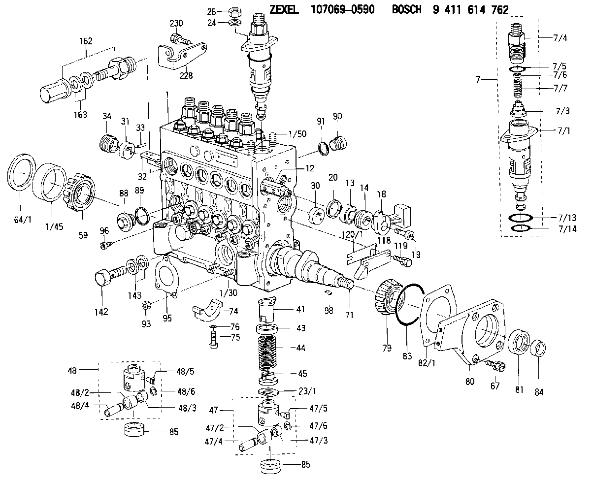
| 1. | [1] | 135005-2220 | PUMP HOUSING |
| 1/30. | [3] | 029040-6020 | STUD |
| 1/45. | [1] | 134311-0000 | SPACER RING |
| 1/50. | [12] | 135024-0000 | STUD |
| 7. | [6] | 135130-6020 | PLUNGER-AND-BARREL ASSY |
| 7/1. | [6] | 135176-3520 | PLUNGER-AND-BARREL ASSY M36 |
| 7/3. | [6] | 135182-0420 | VALVE MM6 |
| 7/4. | [6] | 135116-0100 | FITTING |
| 7/5. | [6] | 029632-0030 | O-RING |
| 7/6. | [6] | 134117-2100 | FILLER PIECE |
| 7/7. | [6] | 134112-2900 | COILED SPRING |
| 7/13. | [6] | 135134-0000 | O-RING |
| 7/14. | [6] | 135134-0500 | O-RING |
| 12. | [1] | 135227-0020 | CONTROL ROD |
| 13. | [1] | 134227-1400 | BEARING PLATE |
| 14. | [1] | 134227-0300 | BUSHING |
| 18. | [1] | 135227-1500 | CONNECTOR |
| 19. | [1] | 139005-0300 | HEX-SOCKET-HEAD CAP SCREW |
| 20. | [1] | 139320-0000 | PLAIN WASHER |
| 23/1. | [0] | 139415-0000 | SHIM D19&10T0.500 |
| 23/1. | [0] | 139415-0100 | SHIM D19&10T0.525 |
| 23/1. | [0] | 139415-0200 | SHIM D19&10T0.550 |
| 23/1. | [0] | 139415-0300 | SHIM D19&10T0.575 |
| 23/1. | [0] | 139415-0400 | SHIM D19&10T0.600 |
| 23/1. | [0] | 139415-0500 | SHIM D19&10T0.625 |
| 23/1. | [0] | 139415-0600 | SHIM D19&10T0.650 |
| 23/1. | [0] | 139415-0700 | SHIM D19&10T0.675 |
| 23/1. | [0] | 139415-0800 | SHIM D19&10T0.700 |
| 23/1. | [0] | 139415-0900 | SHIM D19&10T0.725 |
| 23/1. | [0] | 139415-1000 | SHIM D19&10T0.750 |
| 23/1. | [0] | 139415-1100 | SHIM D19&10T0.775 |
| 23/1. | [0] | 139415-1200 | SHIM D19&10T0.800 |
| 23/1. | [0] | 139415-1300 | SHIM D19&10T0.825 |
| 23/1. | [0] | 139415-1400 | SHIM D19&10T0.850 |
| 23/1. | [0] | 139415-1500 | SHIM D19&10T0.875 |
| 23/1. | [0] | 139415-1600 | SHIM D19&10T0.900 |
| 23/1. | [0] | 139415-1700 | SHIM D19&10T0.925 |
| 23/1. | [0] | 139415-1800 | SHIM D19&10T0.950 |
| 23/1. | [0] | 139415-1900 | SHIM D19&10T0.975 |
| 23/1. | [0] | 139415-2000 | SHIM D19&10T1.000 |
| 23/1. | [0] | 139415-2100 | SHIM D19&10T1.025 |
| 23/1. | [0] | 139415-2200 | SHIM D19&10T1.050 |
| 23/1. | [0] | 139415-2300 | SHIM D19&10T1.075 |
| 23/1. | [0] | 139415-2400 | SHIM D19&10T1.100 |
| 23/1. | [0] | 139415-2500 | SHIM D19&10T1.125 |
| 23/1. | [0] | 139415-2600 | SHIM D19&10T1.150 |
| 23/1. | [0] | 139415-2700 | SHIM D19&10T1.175 |
| 23/1. | [0] | 139415-2800 | SHIM D19&10T1.200 |
| 23/1. | [0] | 139415-2900 | SHIM D19&10T1.225 |
| 23/1. | [0] | 139415-3000 | SHIM D19&10T1.250 |
| 23/1. | [0] | 139415-3100 | SHIM D19&10T1.275 |
| 23/1. | [0] | 139415-3200 | SHIM D19&10T1.300 |
| 23/1. | [0] | 139415-3300 | SHIM D19&10T1.325 |
| 23/1. | [0] | 139415-3400 | SHIM D19&10T1.350 |
| 23/1. | [0] | 139415-3500 | SHIM D19&10T1.375 |
| 23/1. | [0] | 139415-3600 | SHIM D19&10T1.400 |
| 23/1. | [0] | 139415-3700 | SHIM D19&10T1.425 |
| 23/1. | [0] | 139415-3800 | SHIM D19&10T1.450 |
| 23/1. | [0] | 139415-3900 | SHIM D19&10T1.475 |
| 23/1. | [0] | 139415-4000 | SHIM D19&10T1.500 |
| 23/1. | [0] | 139415-4100 | SHIM D19&10T1.525 |
| 23/1. | [0] | 139415-4200 | SHIM D19&10T1.550 |
| 23/1. | [0] | 139415-4300 | SHIM D19&10T1.575 |
| 23/1. | [0] | 139415-4400 | SHIM D19&10T1.600 |
| 23/1. | [0] | 139415-4500 | SHIM D19&10T1.625 |
| 23/1. | [0] | 139415-4600 | SHIM D19&10T1.650 |
| 23/1. | [0] | 139415-4700 | SHIM D19&10T1.675 |
| 23/1. | [0] | 139415-4800 | SHIM D19&10T1.700 |
| 23/1. | [0] | 139415-4900 | SHIM D19&10T1.725 |
| 23/1. | [0] | 139415-5000 | SHIM D19&10T1.750 |
| 23/1. | [0] | 139415-5100 | SHIM D19&10T1.775 |
| 23/1. | [0] | 139415-5200 | SHIM D19&10T1.800 |
| 23/1. | [0] | 139415-5300 | SHIM D19&10T1.825 |
| 23/1. | [0] | 139415-5400 | SHIM D19&10T1.850 |
| 23/1. | [0] | 139415-5500 | SHIM D19&10T1.875 |
| 23/1. | [0] | 139415-5600 | SHIM D19&10T1.900 |
| 23/1. | [0] | 139415-5700 | SHIM D19&10T1.925 |
| 23/1. | [0] | 139415-5800 | SHIM D19&10T1.950 |
| 23/1. | [0] | 139415-5900 | SHIM D19&10T1.975 |
| 24. | [12] | 134132-0300 | PLAIN WASHER |
| 26. | [12] | 139210-0200 | UNION NUT |
| 30. | [1] | 134001-0000 | BUSHING |
| 31. | [1] | 134001-0600 | BUSHING |
| 32. | [1] | 135256-1120 | CONTROL RACK |
| 33. | [1] | 024030-2030 | BEARING PIN |
| 34. | [1] | 134222-0000 | BUSHING |
| 41. | [6] | 135241-0020 | CONTROL SLEEVE |
| 43. | [6] | 135216-0000 | SLOTTED WASHER |
| 44. | [6] | 135215-0000 | COMPRESSION SPRING |
| 45. | [6] | 135217-0000 | SLOTTED WASHER |
| 47. | [4] | 135200-0120 | TAPPET |
| 47/2. | [4] | 135204-0000 | ROLLER |
| 47/3. | [4] | 135205-0000 | BUSHING |
| 47/4. | [4] | 135203-0000 | BEARING PIN |
| 47/5. | [4] | 135206-0000 | SLIDER |
| 47/6. | [4] | 135208-0000 | LOCKING WASHER |
| 48. | [2] | 135200-0020 | TAPPET |
| 48/2. | [2] | 135204-0000 | ROLLER |
| 48/3. | [2] | 135205-0000 | BUSHING |
| 48/4. | [2] | 135203-0000 | BEARING PIN |
| 48/5. | [2] | 135206-0000 | SLIDER |
| 48/6. | [2] | 135208-0000 | LOCKING WASHER |
| 59. | [1] | 016650-2230 | BEARING PLATE 4T-32205(NSK) |
| 64/1. | [0] | 134303-0000 | SHIM D59.8&43T1.2 |
| 64/1. | [0] | 134303-0100 | SHIM D59.8&43T1.5 |
| 64/1. | [0] | 134303-0200 | SHIM D59.8&43T1.8 |
| 64/1. | [0] | 134303-0300 | SHIM D59.8&43T2.0 |
| 64/1. | [0] | 134303-0400 | SHIM D59.8&43T0.6 |
| 67. | [4] | 139006-5800 | BLEEDER SCREW |
| 71. | [1] | 135360-1400 | CAMSHAFT |
| 74. | [3] | 135306-0000 | BEARING SHELL |
| 75. | [6] | 010206-2540 | HEX-SOCKET-HEAD CAP SCREW |
| 76. | [6] | 026506-1040 | GASKET |
| 79. | [1] | 016650-2230 | BEARING PLATE 4T-32205(NSK) |
| 80. | [1] | 135316-0500 | COVER |
| 81. | [1] | 139625-0000 | PACKING RING |
| 82/1. | [0] | 135314-0000 | SHIM T0.10 |
| 82/1. | [0] | 135314-0100 | SHIM T0.12 |
| 82/1. | [0] | 135314-0200 | SHIM T0.14 |
| 82/1. | [0] | 135314-0300 | SHIM T0.16 |
| 82/1. | [0] | 135314-0400 | SHIM T0.18 |
| 82/1. | [0] | 135314-0500 | SHIM T0.3 |
| 82/1. | [0] | 135314-0600 | SHIM T0.5 |
| 83. | [1] | 029635-5010 | O-RING |
| 84. | [1] | 134563-0900 | SLIDING PIECE |
| 85. | [6] | 135034-0000 | CAPSULE |
| 85. | [6] | 135034-0000 | CAPSULE |
| 88. | [6] | 135045-0000 | CAPSULE |
| 89. | [6] | 026522-2740 | GASKET |
| 90. | [7] | 135045-0100 | CAPSULE |
| 91. | [7] | 026514-1840 | GASKET |
| 93. | [3] | 139206-0400 | UNION NUT |
| 95. | [1] | 131041-0800 | GASKET |
| 96. | [6] | 134047-0000 | CAPSULE |
| 98. | [1] | 029470-5010 | WOODRUFF KEY |
| 118. | [1] | 135496-0300 | POINTER |
| 119. | [2] | 020006-1440 | BLEEDER SCREW |
| 120/1. | [0] | 139400-0500 | SHIM T0.20 |
| 120/1. | [0] | 139400-0600 | SHIM T0.30 |
| 120/1. | [0] | 139400-0700 | SHIM T0.50 |
| 120/1. | [0] | 139400-0800 | SHIM T1.00 |
| 142. | [1] | 029731-0180 | EYE BOLT |
| 143. | [2] | 026510-1340 | GASKET |
| 162. | [1] | 131425-0520 | OVER FLOW VALVE |
| 163. | [2] | 029341-4130 | GASKET |
| 228. | [1] | 135439-1600 | BRACKET |
| 230. | [2] | 020106-1440 | BLEEDER SCREW |
Include in #1:
107691-2623
as FUEL INJECTION PUMP
Cross reference number
Zexel num
Bosch num
Firm num
Name
107069-0590
ME755067 MITSUBISHI
FUEL-INJECTION PUMP
Q 14CG FUEL INJECTION PUMP TICS MD-TI6 TICS
Q 14CG FUEL INJECTION PUMP TICS MD-TI6 TICS
Information:
Start By:a. remove timing gear coverb. remove push rods and valve lifters 1. Remove air compressor outlet hose (1). (Not applicable).2. Remove air compressor air inlet tube (3). (Not applicable).3. Remove air compressor coolant outlet tube (4). (Not applicable)4. Remove turbocharger oil return tube (2). 5. Use Tooling (A) to remove studs (5).6. Turn the flywheel with Tool (B), and remove each bolt (6) as it becomes accessible.7. Turn the flywheel with Tool (B) until the "V" marks on the front timing gears are in alignment.8. Install Tooling (C) through the holes for studs (5) into camshaft rear gear (7).
Tooling (C) must be used to prevent the loss of rear balance weight timing and to keep the camshaft rear gear in place when the camshaft is removed.
9. Tighten Tooling (C) evenly to remove the camshaft rear gear from the camshaft. 10. Remove thrust plate (8).
Be careful not to damage the camshaft bearings. Do not pry the camshaft out of the cylinder block. If resistance to camshaft removal occurs, turn the camshaft so the lobes will align the bearing journals with the camshaft bearing bores.
11. Carefully remove the camshaft and gear (9) from the cylinder block.12. If removal of the camshaft gear is necessary, place the camshaft and gear in a hydraulic press. Place Tool (D) over the camshaft, and press against it to remove the camshaft from the gear.
Be careful not to scratch or mar the finished surfaces of the camshaft.
13. Remove the key from the camshaft.14. If dowel removal is necessary, use Tool (E) to remove the dowel.Install Camshaft
1. Install the key in the camshaft. Be sure the key is seated in the camshaft.2. Install the pin in the rear of the camshaft. Install the pin to a height of 8.51 to 9.01 mm (.335 to .355 in).3. Heat the camshaft drive gear to a maximum temperature of 204° C (400° F), align the groove in the drive gear with the key in the camshaft, and install the camshaft drive gear with the timing marks away from the camshaft.4. Put clean engine oil on the camshaft bearing journals and lobes.5. Carefully install the camshaft into the cylinder block. Do not force the camshaft into position. If resistance to camshaft installation occurs, turn the camshaft so the lobes will align the bearing journals with the camshaft bearing bores. 6. Align the "V" marks on camshaft drive gear (2) and idler gear (3).7. Install thrust plate (1) to hold the camshaft and camshaft drive gear (2) in the cylinder block. 8. Loosen the bolts Tool (B) that hold camshaft rear gear (5) so camshaft rear gear (5) will engage the dowel on the rear of the camshaft.9. After the dowel is engaged, remove Tool (B), and install bolts (4).10. Use Tool (A) to turn the flywheel, and install each of four bolts (4). Tighten bolts (4) to a torque of 23 to 31 N m (17 to 23 lb ft).11. Put 5P-3413 Pipe Sealant with "Teflon" on the