Information fuel-injection pump
BOSCH
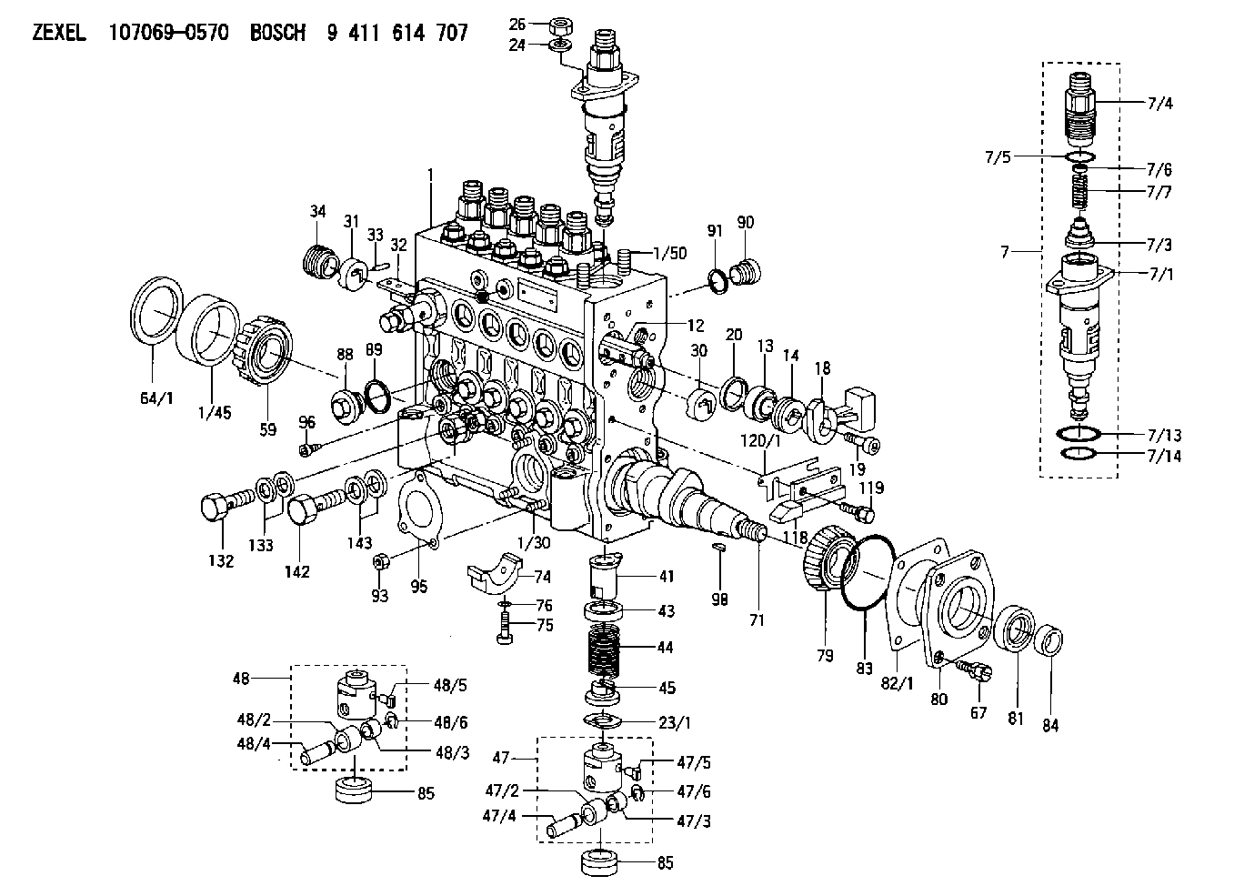
9 411 614 707
9411614707
ZEXEL
107069-0570
1070690570
HINO
221005430A
221005430a
Rating:
Scheme ###:
| 1. | [1] | 135005-2720 | PUMP HOUSING |
| 1/30. | [3] | 029040-6020 | STUD |
| 1/45. | [1] | 134311-0000 | SPACER RING |
| 1/50. | [12] | 135024-0000 | STUD |
| 7. | [6] | 135130-5320 | PLUNGER-AND-BARREL ASSY |
| 7/1. | [1] | 135176-3620 | PLUNGER-AND-BARREL ASSY |
| 7/3. | [1] | 135182-0220 | VALVE |
| 7/4. | [1] | 135116-0100 | FITTING |
| 7/5. | [1] | 029632-0030 | O-RING |
| 7/6. | [1] | 134117-2100 | FILLER PIECE |
| 7/7. | [1] | 134112-4000 | COMPRESSION SPRING |
| 7/13. | [1] | 135134-0000 | O-RING |
| 7/14. | [1] | 135134-0500 | O-RING |
| 12. | [1] | 135227-0020 | CONTROL ROD |
| 13. | [1] | 134227-1400 | BEARING PLATE |
| 14. | [1] | 134227-0300 | BUSHING |
| 18. | [1] | 135227-1500 | CONNECTOR |
| 19. | [1] | 139005-0300 | HEX-SOCKET-HEAD CAP SCREW |
| 20. | [1] | 139320-0000 | PLAIN WASHER |
| 23/1. | [0] | 139415-0000 | SHIM D19&10T0.500 |
| 23/1. | [0] | 139415-0100 | SHIM D19&10T0.525 |
| 23/1. | [0] | 139415-0200 | SHIM D19&10T0.550 |
| 23/1. | [0] | 139415-0300 | SHIM D19&10T0.575 |
| 23/1. | [0] | 139415-0400 | SHIM D19&10T0.600 |
| 23/1. | [0] | 139415-0500 | SHIM D19&10T0.625 |
| 23/1. | [0] | 139415-0600 | SHIM D19&10T0.650 |
| 23/1. | [0] | 139415-0700 | SHIM D19&10T0.675 |
| 23/1. | [0] | 139415-0800 | SHIM D19&10T0.700 |
| 23/1. | [0] | 139415-0900 | SHIM D19&10T0.725 |
| 23/1. | [0] | 139415-1000 | SHIM D19&10T0.750 |
| 23/1. | [0] | 139415-1100 | SHIM D19&10T0.775 |
| 23/1. | [0] | 139415-1200 | SHIM D19&10T0.800 |
| 23/1. | [0] | 139415-1300 | SHIM D19&10T0.825 |
| 23/1. | [0] | 139415-1400 | SHIM D19&10T0.850 |
| 23/1. | [0] | 139415-1500 | SHIM D19&10T0.875 |
| 23/1. | [0] | 139415-1600 | SHIM D19&10T0.900 |
| 23/1. | [0] | 139415-1700 | SHIM D19&10T0.925 |
| 23/1. | [0] | 139415-1800 | SHIM D19&10T0.950 |
| 23/1. | [0] | 139415-1900 | SHIM D19&10T0.975 |
| 23/1. | [0] | 139415-2000 | SHIM D19&10T1.000 |
| 23/1. | [0] | 139415-2100 | SHIM D19&10T1.025 |
| 23/1. | [0] | 139415-2200 | SHIM D19&10T1.050 |
| 23/1. | [0] | 139415-2300 | SHIM D19&10T1.075 |
| 23/1. | [0] | 139415-2400 | SHIM D19&10T1.100 |
| 23/1. | [0] | 139415-2500 | SHIM D19&10T1.125 |
| 23/1. | [0] | 139415-2600 | SHIM D19&10T1.150 |
| 23/1. | [0] | 139415-2700 | SHIM D19&10T1.175 |
| 23/1. | [0] | 139415-2800 | SHIM D19&10T1.200 |
| 23/1. | [0] | 139415-2900 | SHIM D19&10T1.225 |
| 23/1. | [0] | 139415-3000 | SHIM D19&10T1.250 |
| 23/1. | [0] | 139415-3100 | SHIM D19&10T1.275 |
| 23/1. | [0] | 139415-3200 | SHIM D19&10T1.300 |
| 23/1. | [0] | 139415-3300 | SHIM D19&10T1.325 |
| 23/1. | [0] | 139415-3400 | SHIM D19&10T1.350 |
| 23/1. | [0] | 139415-3500 | SHIM D19&10T1.375 |
| 23/1. | [0] | 139415-3600 | SHIM D19&10T1.400 |
| 23/1. | [0] | 139415-3700 | SHIM D19&10T1.425 |
| 23/1. | [0] | 139415-3800 | SHIM D19&10T1.450 |
| 23/1. | [0] | 139415-3900 | SHIM D19&10T1.475 |
| 23/1. | [0] | 139415-4000 | SHIM D19&10T1.500 |
| 23/1. | [0] | 139415-4100 | SHIM D19&10T1.525 |
| 23/1. | [0] | 139415-4200 | SHIM D19&10T1.550 |
| 23/1. | [0] | 139415-4300 | SHIM D19&10T1.575 |
| 23/1. | [0] | 139415-4400 | SHIM D19&10T1.600 |
| 23/1. | [0] | 139415-4500 | SHIM D19&10T1.625 |
| 23/1. | [0] | 139415-4600 | SHIM D19&10T1.650 |
| 23/1. | [0] | 139415-4700 | SHIM D19&10T1.675 |
| 23/1. | [0] | 139415-4800 | SHIM D19&10T1.700 |
| 23/1. | [0] | 139415-4900 | SHIM D19&10T1.725 |
| 23/1. | [0] | 139415-5000 | SHIM D19&10T1.750 |
| 23/1. | [0] | 139415-5100 | SHIM D19&10T1.775 |
| 23/1. | [0] | 139415-5200 | SHIM D19&10T1.800 |
| 23/1. | [0] | 139415-5300 | SHIM D19&10T1.825 |
| 23/1. | [0] | 139415-5400 | SHIM D19&10T1.850 |
| 23/1. | [0] | 139415-5500 | SHIM D19&10T1.875 |
| 23/1. | [0] | 139415-5600 | SHIM D19&10T1.900 |
| 23/1. | [0] | 139415-5700 | SHIM D19&10T1.925 |
| 23/1. | [0] | 139415-5800 | SHIM D19&10T1.950 |
| 23/1. | [0] | 139415-5900 | SHIM D19&10T1.975 |
| 24. | [12] | 134132-0300 | PLAIN WASHER D20&11T2.5 |
| 26. | [12] | 139210-0200 | UNION NUT |
| 30. | [1] | 134001-0000 | BUSHING |
| 31. | [1] | 134001-0600 | BUSHING |
| 32. | [1] | 135256-1320 | CONTROL RACK |
| 33. | [1] | 024030-2030 | BEARING PIN |
| 34. | [1] | 134222-0000 | BUSHING |
| 41. | [6] | 135241-0020 | CONTROL SLEEVE |
| 43. | [6] | 135216-0000 | SLOTTED WASHER |
| 44. | [6] | 135215-0000 | COMPRESSION SPRING |
| 45. | [6] | 135217-0000 | SLOTTED WASHER |
| 47. | [4] | 135200-0220 | TAPPET |
| 47/2. | [1] | 135204-0000 | ROLLER |
| 47/3. | [1] | 135205-0000 | BUSHING |
| 47/4. | [1] | 135203-0000 | BEARING PIN |
| 47/5. | [1] | 135206-0000 | SLIDER |
| 47/6. | [1] | 135208-0000 | LOCKING WASHER |
| 48. | [2] | 135200-0320 | TAPPET |
| 48/2. | [1] | 135204-0000 | ROLLER |
| 48/3. | [1] | 135205-0000 | BUSHING |
| 48/4. | [1] | 135203-0000 | BEARING PIN |
| 48/5. | [1] | 135206-0000 | SLIDER |
| 48/6. | [1] | 135208-0000 | LOCKING WASHER |
| 59. | [1] | 016650-2230 | BEARING PLATE |
| 64/1. | [0] | 134303-0000 | SHIM D59.8&43T1.2 |
| 64/1. | [0] | 134303-0100 | SHIM D59.8&43T1.5 |
| 64/1. | [0] | 134303-0200 | SHIM D59.8&43T1.8 |
| 64/1. | [0] | 134303-0300 | SHIM D59.8&43T2.0 |
| 64/1. | [0] | 134303-0400 | SHIM D59.8&43T0.6 |
| 67. | [4] | 139006-4200 | BLEEDER SCREW |
| 71. | [1] | 135360-2200 | CAMSHAFT |
| 74. | [3] | 135306-0000 | BEARING SHELL |
| 75. | [6] | 010206-2540 | HEX-SOCKET-HEAD CAP SCREW |
| 76. | [6] | 026506-1040 | GASKET D9.9&6.2T1 |
| 79. | [1] | 016650-2230 | BEARING PLATE |
| 80. | [1] | 135316-0000 | COVER |
| 81. | [1] | 139625-0000 | PACKING RING |
| 82/1. | [0] | 135314-0000 | SHIM T0.10 |
| 82/1. | [0] | 135314-0100 | SHIM T0.12 |
| 82/1. | [0] | 135314-0200 | SHIM T0.14 |
| 82/1. | [0] | 135314-0300 | SHIM T0.16 |
| 82/1. | [0] | 135314-0400 | SHIM T0.18 |
| 82/1. | [0] | 135314-0500 | SHIM T0.3 |
| 82/1. | [0] | 135314-0600 | SHIM T0.5 |
| 83. | [1] | 029635-5010 | O-RING |
| 84. | [1] | 134563-0900 | SLIDING PIECE |
| 85. | [6] | 135034-0000 | CAPSULE |
| 85. | [6] | 135034-0000 | CAPSULE |
| 88. | [6] | 135045-0000 | CAPSULE |
| 89. | [6] | 026522-2740 | GASKET D26.9&22.2T1 |
| 90. | [7] | 135045-0100 | CAPSULE |
| 91. | [7] | 026514-1840 | GASKET D17.9&14.2T1 |
| 93. | [3] | 139206-0400 | UNION NUT |
| 95. | [1] | 131041-0800 | GASKET |
| 96. | [6] | 134047-0000 | CAPSULE |
| 98. | [1] | 025805-1910 | WOODRUFF KEY |
| 118. | [1] | 135496-1200 | POINTER |
| 119. | [2] | 020006-1440 | BLEEDER SCREW |
| 120/1. | [0] | 139400-0500 | SHIM T0.20 |
| 120/1. | [0] | 139400-0600 | SHIM T0.30 |
| 120/1. | [0] | 139400-0700 | SHIM T0.50 |
| 120/1. | [0] | 139400-0800 | SHIM T1.00 |
| 132. | [1] | 135430-0400 | EYE BOLT |
| 133. | [2] | 139514-0300 | GASKET |
| 142. | [1] | 134430-0200 | EYE BOLT |
| 143. | [2] | 139510-0300 | GASKET |
Cross reference number
Zexel num
Bosch num
Firm num
Name
Information:
1. Disconnect hose (1) at governor control cylinder (2).2. Remove pin (4).3. Remove governor control cylinder (2).4. Note the position of linkage (3) in the lever, and remove linkage (3). The following steps are for installation of the governor control cylinder.5. Adjust linkage (3) so the distance between rod end centers is 84.07 mm (3.309 in).6. Install linkage (3) in its original position in the lever.7. Be sure lever (5) on the governor shaft is at 15 degrees from vertical (CW when viewed from the left side of the machine) with engine at low idle.8. Install control cylinder (2). Install pin (4) through link (3) and lever (5).9. Connect hose (1) to governor control cylinder (2).10. Adjust linkage (3) so lever (5) is at low idle when governor control cylinder is fully retracted.Disassemble & Assemble Governor Control Cylinder
Start By:a. remove governor control cylinder 1. Remove cover (1).
A spring force of 44.5 N (10 lb) will be released when the bolt that holds piston (8) is removed. Hold the components of the governor control cylinder to prevent unexpected movement of components and personal injury.
2. Remove the bolt that holds piston (6), and remove the piston and springs.3. Remove O-ring seal (2) and sleeve (5).4. Remove seals (3) and (4) from piston (6). The following steps are for the assembly of the governor control cylinder.5. Install lip-type seal (3) and "T" seal on the piston (6). Install the lip-type seal with the lip facing the cylinder pressure source.6. Install shell (5) in the air chamber body.7. Put 5P-0960 Multipurpose Grease inside the shell.8. Carefully install piston (6) and springs into the air chamber body.9. Install the bolt to hold the piston.10. Install O-ring seal (2) and cover (1).End By:a. install governor control cylinder