Information fuel-injection pump
BOSCH
9 411 614 664
9411614664
ZEXEL
107069-0510
1070690510
Rating:
Scheme ###:
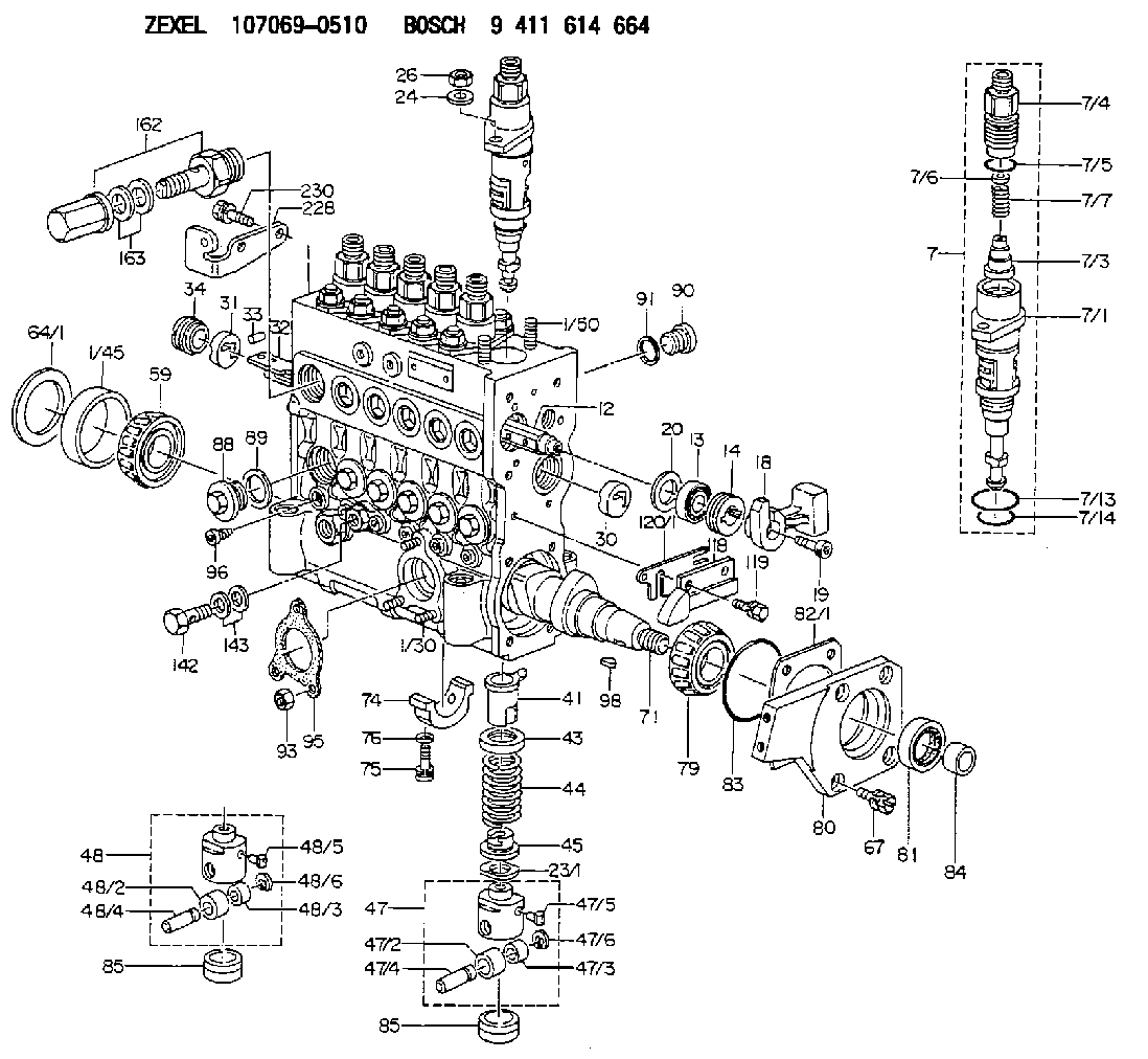
| 1. | [1] | 135005-2220 | PUMP HOUSING |
| 1/30. | [3] | 029040-6020 | STUD |
| 1/45. | [1] | 134311-0000 | SPACER RING |
| 1/50. | [12] | 135024-0000 | STUD |
| 7. | [6] | 135130-4320 | PLUNGER-AND-BARREL ASSY |
| 7/1. | [1] | 135176-3520 | PLUNGER-AND-BARREL ASSY |
| 7/3. | [1] | 135182-0120 | VALVE |
| 7/4. | [1] | 135116-0100 | FITTING |
| 7/5. | [1] | 029632-0030 | O-RING |
| 7/6. | [1] | 134117-2100 | FILLER PIECE |
| 7/7. | [1] | 134112-2900 | COILED SPRING |
| 7/13. | [1] | 135134-0000 | O-RING |
| 7/14. | [1] | 135134-0500 | O-RING |
| 12. | [1] | 135227-0020 | CONTROL ROD |
| 13. | [1] | 134227-1400 | BEARING PLATE |
| 14. | [1] | 134227-0300 | BUSHING |
| 18. | [1] | 135227-1500 | CONNECTOR |
| 19. | [1] | 139005-0300 | HEX-SOCKET-HEAD CAP SCREW |
| 20. | [1] | 139320-0000 | PLAIN WASHER |
| 23/1. | [0] | 139415-0000 | SHIM D19&10T0.500 |
| 23/1. | [0] | 139415-0100 | SHIM D19&10T0.525 |
| 23/1. | [0] | 139415-0200 | SHIM D19&10T0.550 |
| 23/1. | [0] | 139415-0300 | SHIM D19&10T0.575 |
| 23/1. | [0] | 139415-0400 | SHIM D19&10T0.600 |
| 23/1. | [0] | 139415-0500 | SHIM D19&10T0.625 |
| 23/1. | [0] | 139415-0600 | SHIM D19&10T0.650 |
| 23/1. | [0] | 139415-0700 | SHIM D19&10T0.675 |
| 23/1. | [0] | 139415-0800 | SHIM D19&10T0.700 |
| 23/1. | [0] | 139415-0900 | SHIM D19&10T0.725 |
| 23/1. | [0] | 139415-1000 | SHIM D19&10T0.750 |
| 23/1. | [0] | 139415-1100 | SHIM D19&10T0.775 |
| 23/1. | [0] | 139415-1200 | SHIM D19&10T0.800 |
| 23/1. | [0] | 139415-1300 | SHIM D19&10T0.825 |
| 23/1. | [0] | 139415-1400 | SHIM D19&10T0.850 |
| 23/1. | [0] | 139415-1500 | SHIM D19&10T0.875 |
| 23/1. | [0] | 139415-1600 | SHIM D19&10T0.900 |
| 23/1. | [0] | 139415-1700 | SHIM D19&10T0.925 |
| 23/1. | [0] | 139415-1800 | SHIM D19&10T0.950 |
| 23/1. | [0] | 139415-1900 | SHIM D19&10T0.975 |
| 23/1. | [0] | 139415-2000 | SHIM D19&10T1.000 |
| 23/1. | [0] | 139415-2100 | SHIM D19&10T1.025 |
| 23/1. | [0] | 139415-2200 | SHIM D19&10T1.050 |
| 23/1. | [0] | 139415-2300 | SHIM D19&10T1.075 |
| 23/1. | [0] | 139415-2400 | SHIM D19&10T1.100 |
| 23/1. | [0] | 139415-2500 | SHIM D19&10T1.125 |
| 23/1. | [0] | 139415-2600 | SHIM D19&10T1.150 |
| 23/1. | [0] | 139415-2700 | SHIM D19&10T1.175 |
| 23/1. | [0] | 139415-2800 | SHIM D19&10T1.200 |
| 23/1. | [0] | 139415-2900 | SHIM D19&10T1.225 |
| 23/1. | [0] | 139415-3000 | SHIM D19&10T1.250 |
| 23/1. | [0] | 139415-3100 | SHIM D19&10T1.275 |
| 23/1. | [0] | 139415-3200 | SHIM D19&10T1.300 |
| 23/1. | [0] | 139415-3300 | SHIM D19&10T1.325 |
| 23/1. | [0] | 139415-3400 | SHIM D19&10T1.350 |
| 23/1. | [0] | 139415-3500 | SHIM D19&10T1.375 |
| 23/1. | [0] | 139415-3600 | SHIM D19&10T1.400 |
| 23/1. | [0] | 139415-3700 | SHIM D19&10T1.425 |
| 23/1. | [0] | 139415-3800 | SHIM D19&10T1.450 |
| 23/1. | [0] | 139415-3900 | SHIM D19&10T1.475 |
| 23/1. | [0] | 139415-4000 | SHIM D19&10T1.500 |
| 23/1. | [0] | 139415-4100 | SHIM D19&10T1.525 |
| 23/1. | [0] | 139415-4200 | SHIM D19&10T1.550 |
| 23/1. | [0] | 139415-4300 | SHIM D19&10T1.575 |
| 23/1. | [0] | 139415-4400 | SHIM D19&10T1.600 |
| 23/1. | [0] | 139415-4500 | SHIM D19&10T1.625 |
| 23/1. | [0] | 139415-4600 | SHIM D19&10T1.650 |
| 23/1. | [0] | 139415-4700 | SHIM D19&10T1.675 |
| 23/1. | [0] | 139415-4800 | SHIM D19&10T1.700 |
| 23/1. | [0] | 139415-4900 | SHIM D19&10T1.725 |
| 23/1. | [0] | 139415-5000 | SHIM D19&10T1.750 |
| 23/1. | [0] | 139415-5100 | SHIM D19&10T1.775 |
| 23/1. | [0] | 139415-5200 | SHIM D19&10T1.800 |
| 23/1. | [0] | 139415-5300 | SHIM D19&10T1.825 |
| 23/1. | [0] | 139415-5400 | SHIM D19&10T1.850 |
| 23/1. | [0] | 139415-5500 | SHIM D19&10T1.875 |
| 23/1. | [0] | 139415-5600 | SHIM D19&10T1.900 |
| 23/1. | [0] | 139415-5700 | SHIM D19&10T1.925 |
| 23/1. | [0] | 139415-5800 | SHIM D19&10T1.950 |
| 23/1. | [0] | 139415-5900 | SHIM D19&10T1.975 |
| 24. | [12] | 134132-0300 | PLAIN WASHER D20&11T2.5 |
| 26. | [12] | 139210-0200 | UNION NUT |
| 30. | [1] | 134001-0000 | BUSHING |
| 31. | [1] | 134001-0600 | BUSHING |
| 32. | [1] | 135256-1020 | CONTROL RACK |
| 33. | [1] | 024030-2030 | BEARING PIN |
| 34. | [1] | 134222-0000 | BUSHING |
| 41. | [6] | 135241-0020 | CONTROL SLEEVE |
| 43. | [6] | 135216-0000 | SLOTTED WASHER |
| 44. | [6] | 135215-0000 | COMPRESSION SPRING |
| 45. | [6] | 135217-0000 | SLOTTED WASHER |
| 47. | [4] | 135200-0120 | TAPPET |
| 47/2. | [1] | 135204-0000 | ROLLER |
| 47/3. | [1] | 135205-0000 | BUSHING |
| 47/4. | [1] | 135203-0000 | BEARING PIN |
| 47/5. | [1] | 135206-0000 | SLIDER |
| 47/6. | [1] | 135208-0000 | LOCKING WASHER |
| 48. | [2] | 135200-0020 | TAPPET |
| 48/2. | [1] | 135204-0000 | ROLLER |
| 48/3. | [1] | 135205-0000 | BUSHING |
| 48/4. | [1] | 135203-0000 | BEARING PIN |
| 48/5. | [1] | 135206-0000 | SLIDER |
| 48/6. | [1] | 135208-0000 | LOCKING WASHER |
| 59. | [1] | 016650-2230 | BEARING PLATE |
| 64/1. | [0] | 134303-0000 | SHIM D59.8&43T1.2 |
| 64/1. | [0] | 134303-0100 | SHIM D59.8&43T1.5 |
| 64/1. | [0] | 134303-0200 | SHIM D59.8&43T1.8 |
| 64/1. | [0] | 134303-0300 | SHIM D59.8&43T2.0 |
| 64/1. | [0] | 134303-0400 | SHIM D59.8&43T0.6 |
| 67. | [4] | 139006-5800 | BLEEDER SCREW |
| 71. | [1] | 135360-1400 | CAMSHAFT |
| 74. | [3] | 135306-0000 | BEARING SHELL |
| 75. | [6] | 010206-2540 | HEX-SOCKET-HEAD CAP SCREW M6P1L25 |
| 76. | [6] | 026506-1040 | GASKET D9.9&6.2T1 |
| 79. | [1] | 016650-2230 | BEARING PLATE |
| 80. | [1] | 135316-0500 | COVER |
| 81. | [1] | 139625-0000 | PACKING RING |
| 82/1. | [0] | 135314-0000 | SHIM T0.10 |
| 82/1. | [0] | 135314-0100 | SHIM T0.12 |
| 82/1. | [0] | 135314-0200 | SHIM T0.14 |
| 82/1. | [0] | 135314-0300 | SHIM T0.16 |
| 82/1. | [0] | 135314-0400 | SHIM T0.18 |
| 82/1. | [0] | 135314-0500 | SHIM T0.3 |
| 82/1. | [0] | 135314-0600 | SHIM T0.5 |
| 83. | [1] | 029635-5010 | O-RING |
| 84. | [1] | 134563-0900 | SLIDING PIECE |
| 85. | [6] | 135034-0000 | CAPSULE |
| 85. | [6] | 135034-0000 | CAPSULE |
| 88. | [6] | 135045-0000 | CAPSULE |
| 89. | [6] | 026522-2740 | GASKET D26.9&22.2T1 |
| 90. | [7] | 135045-0100 | CAPSULE |
| 91. | [7] | 026514-1840 | GASKET D17.9&14.2T1 |
| 93. | [3] | 139206-0400 | UNION NUT |
| 95. | [1] | 131041-0800 | GASKET |
| 96. | [6] | 134047-0000 | CAPSULE |
| 98. | [1] | 025805-1910 | WOODRUFF KEY |
| 118. | [1] | 135496-0500 | POINTER |
| 119. | [2] | 029010-6740 | BLEEDER SCREW |
| 120/1. | [0] | 139400-0500 | SHIM T0.20 |
| 120/1. | [0] | 139400-0600 | SHIM T0.30 |
| 120/1. | [0] | 139400-0700 | SHIM T0.50 |
| 120/1. | [0] | 139400-0800 | SHIM T1.00 |
| 142. | [1] | 029731-0180 | EYE BOLT |
| 143. | [2] | 026510-1340 | GASKET D13.4&10.2T1 |
| 162. | [1] | 131425-0520 | OVER FLOW VALVE |
| 163. | [2] | 029341-4130 | GASKET D20&13.8T2* |
| 228. | [1] | 135439-1600 | BRACKET |
| 230. | [2] | 020106-1440 | BLEEDER SCREW M6P1.0L14 |
Include in #1:
107692-2290
as FUEL INJECTION PUMP
Cross reference number
Zexel num
Bosch num
Firm num
Name
107069-0510
9 411 614 664
FUEL-INJECTION PUMP
* Q
* Q
Information:
1. Remove plug (1) from the fuel injection pump housing.2. Use Tool (D) to loosen nut (2) for the fuel injection pump to be removed. Disconnect the fuel injection line nuts, and remove the felt washer. 3. Install Tool (A) in the fuel pump housing as shown with the square end down. Use a small amount of hand force to push down on Tool (A) while the control lever is moved forward to the "FUEL ON" position. Rack travel will stop in the center (zero) position. Hold a light forward force on the governor control lever to keep the fuel racks in the center (zero) position.4. Use Tool (B) to remove bushing (3) from the fuel injection pump housing. 5. Remove bushing (3) and O-ring seal (4).
When injection pumps, spacers and lifters are removed from the injection pump housing, keep the parts of each pump together so they can be installed in their original location.
6. Use Tool (C) to remove fuel injection pump (5). 7. Remove spacer (6) from the fuel injection pump housing. Make a note of the position from which each spacer was removed so each spacer can be installed in its original position.
Be careful when the fuel injection pumps are disassembled. Do not damage the surfaces of the plungers, barrels and bonnets. Any scratches will cause leakage inside the fuel injection pump. The plunger and barrel for each pump are made as a set. Do not put the plunger of one pump in the barrel of another pump. The check assemblies are made as a set. Do not mix the parts of the different check assemblies. Do not remove or make any adjustments of the gear segment on the plunger. It has been preset at the factory. If one part has wear, install a complete new pump assembly. Be careful when the plunger is put into the bore of the barrel.
8. Disassemble the fuel injection pump as follows: Remove ring (7). Separate bonnet (10) from barrel (9). Remove the spring and the check assembly from the bonnet. Remove plunger (8), the washer and spring from barrel (9).Install Fuel Injection Pumps
1. Inspect all parts for wear or damage. The plunger and barrel are serviced only as an assembly. 2. Put clean diesel fuel on plunger (1). Put plunger (1), washer (6) and spring (2) in position on barrel (3).3. Put check valve assembly (7) and spring (8) in bonnet (9). Connect bonnet (9) and barrel (3) together with ring (4). 4. Put spacer (10) into position in the pump housing bore. Be sure the correct spacer is with each pump. 5. Note the location of dowels (11) and (12) in the fuel injection pump housing. These dowels are for alignment of the fuel injection pump. 6. Slot (13) in gear segment (5) must align with dowel (11).7. Groove (14) must engage with dowel (12). 8. Use Tool (A) to put the fuel racks in the center (zero) position. See Remove Fuel Injection Pumps.9. Use Tool
Have questions with 107069-0510?
Group cross 107069-0510 ZEXEL
Mitsubishi
107069-0510
9 411 614 664
FUEL-INJECTION PUMP