Information fuel-injection pump
BOSCH
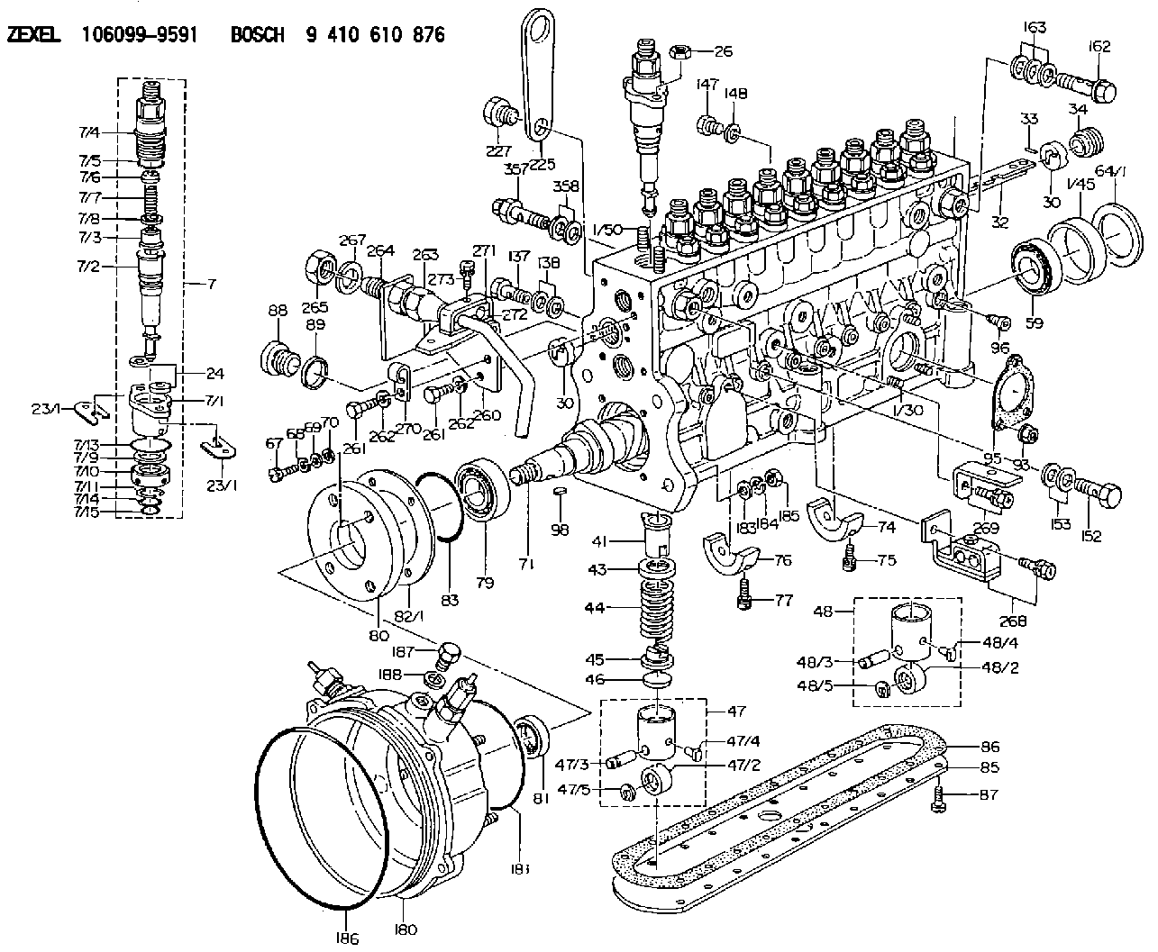
9 410 610 876
9410610876
ZEXEL
106099-9591
1060999591
Rating:
Scheme ###:
| 1. | [1] | 134056-0921 | PUMP HOUSING |
| 1/2. | [1] | 131002-4900 | ADAPTOR |
| 1/3. | [1] | 131002-4900 | ADAPTOR |
| 1/8. | [1] | 131002-6200 | ADAPTOR |
| 1/10. | [1] | 134026-0000 | CAPSULE |
| 1/11. | [1] | 134026-0000 | CAPSULE |
| 1/12. | [1] | 134026-0000 | CAPSULE |
| 1/14. | [1] | 131002-4900 | ADAPTOR |
| 1/30. | [3] | 029040-6020 | STUD |
| 1/45. | [1] | 134311-0000 | SPACER RING |
| 1/50. | [20] | 134138-0000 | STUD |
| 7. | [10] | 134150-5620 | PLUNGER-AND-BARREL ASSY |
| 7/1. | [1] | 134131-1920 | FLANGE BUSHING |
| 7/2. | [1] | 134153-4020 | PLUNGER-AND-BARREL ASSY |
| 7/3. | [1] | 134180-0420 | VALVE |
| 7/4. | [1] | 134116-5600 | FITTING |
| 7/5. | [1] | 139722-0200 | O-RING |
| 7/6. | [1] | 134117-2000 | FILLER PIECE |
| 7/7. | [1] | 134112-2900 | COILED SPRING |
| 7/8. | [1] | 134115-0100 | GASKET |
| 7/9. | [1] | 029302-0140 | PLAIN WASHER |
| 7/10. | [1] | 134135-0400 | CAPSULE |
| 7/11. | [1] | 029602-0010 | LOCKING WASHER |
| 7/13. | [1] | 139729-0100 | O-RING |
| 7/14. | [1] | 139715-0300 | O-RING |
| 7/15. | [1] | 139715-0300 | O-RING |
| 23/1. | [0] | 139400-0900 | SHIM T0.500 |
| 23/1. | [0] | 139400-1000 | SHIM T0.525 |
| 23/1. | [0] | 139400-1100 | SHIM T0.550 |
| 23/1. | [0] | 139400-1200 | SHIM T0.575 |
| 23/1. | [0] | 139400-1300 | SHIM T0.600 |
| 23/1. | [0] | 139400-1400 | SHIM T0.625 |
| 23/1. | [0] | 139400-1500 | SHIM T0.650 |
| 23/1. | [0] | 139400-1600 | SHIM T0.675 |
| 23/1. | [0] | 139400-1700 | SHIM T0.700 |
| 23/1. | [0] | 139400-1800 | SHIM T0.725 |
| 23/1. | [0] | 139400-1900 | SHIM T0.750 |
| 23/1. | [0] | 139400-2000 | SHIM T0.775 |
| 23/1. | [0] | 139400-2100 | SHIM T0.800 |
| 23/1. | [0] | 139400-2200 | SHIM T0.825 |
| 23/1. | [0] | 139400-2300 | SHIM T0.850 |
| 23/1. | [0] | 139400-2400 | SHIM T0.875 |
| 23/1. | [0] | 139400-2500 | SHIM T0.900 |
| 23/1. | [0] | 139400-2600 | SHIM T0.925 |
| 23/1. | [0] | 139400-2700 | SHIM T0.950 |
| 23/1. | [0] | 139400-2800 | SHIM T0.975 |
| 23/1. | [0] | 139400-2900 | SHIM T1.000 |
| 23/1. | [0] | 139400-3000 | SHIM T1.025 |
| 23/1. | [0] | 139400-3100 | SHIM T1.050 |
| 23/1. | [0] | 139400-3200 | SHIM T1.075 |
| 23/1. | [0] | 139400-3300 | SHIM T1.100 |
| 23/1. | [0] | 139400-3400 | SHIM T1.125 |
| 23/1. | [0] | 139400-3500 | SHIM T1.150 |
| 23/1. | [0] | 139400-3600 | SHIM T1.175 |
| 23/1. | [0] | 139400-3700 | SHIM T1.200 |
| 23/1. | [0] | 139400-3800 | SHIM T1.225 |
| 23/1. | [0] | 139400-3900 | SHIM T1.250 |
| 23/1. | [0] | 139400-4000 | SHIM T1.275 |
| 23/1. | [0] | 139400-4100 | SHIM T1.300 |
| 23/1. | [0] | 139400-4200 | SHIM T1.325 |
| 23/1. | [0] | 139400-4300 | SHIM T1.350 |
| 23/1. | [0] | 139400-4400 | SHIM T1.375 |
| 23/1. | [0] | 139400-4500 | SHIM T1.400 |
| 23/1. | [0] | 139400-4600 | SHIM T1.425 |
| 23/1. | [0] | 139400-4700 | SHIM T1.450 |
| 23/1. | [0] | 139400-4800 | SHIM T1.475 |
| 23/1. | [0] | 139400-4900 | SHIM T1.500 |
| 23/1. | [0] | 139400-5000 | SHIM T1.525 |
| 23/1. | [0] | 139400-5100 | SHIM T1.550 |
| 23/1. | [0] | 139400-5200 | SHIM T1.575 |
| 23/1. | [0] | 139400-5300 | SHIM T1.600 |
| 23/1. | [0] | 139400-5400 | SHIM T1.625 |
| 23/1. | [0] | 139400-5500 | SHIM T1.650 |
| 23/1. | [0] | 139400-5600 | SHIM T1.675 |
| 23/1. | [0] | 139400-5700 | SHIM T1.700 |
| 23/1. | [0] | 139400-5800 | SHIM T1.725 |
| 23/1. | [0] | 139400-5800 | SHIM T1.725 |
| 23/1. | [0] | 139400-5900 | SHIM T1.750 |
| 23/1. | [0] | 139400-6000 | SHIM T1.775 |
| 23/1. | [0] | 139400-6100 | SHIM T1.800 |
| 23/1. | [0] | 139400-6200 | SHIM T1.825 |
| 23/1. | [0] | 139400-6300 | SHIM T1.850 |
| 23/1. | [0] | 139400-6400 | SHIM T1.875 |
| 23/1. | [0] | 139400-6500 | SHIM T1.900 |
| 23/1. | [0] | 139400-6600 | SHIM T1.925 |
| 23/1. | [0] | 139400-6700 | SHIM T1.950 |
| 23/1. | [0] | 139400-6800 | SHIM T1.975 |
| 24. | [20] | 134132-0300 | PLAIN WASHER D20&11T2.5 |
| 26. | [20] | 013021-0040 | UNION NUT M10P1.5H8 |
| 30. | [2] | 134001-0000 | BUSHING |
| 30. | [2] | 134001-0000 | BUSHING |
| 32. | [1] | 134250-0620 | CONTROL RACK |
| 33. | [1] | 024030-2030 | BEARING PIN |
| 34. | [1] | 134222-0000 | BUSHING |
| 41. | [10] | 134241-0320 | CONTROL SLEEVE |
| 43. | [10] | 134216-0000 | SLOTTED WASHER |
| 44. | [10] | 134215-0800 | COMPRESSION SPRING |
| 45. | [10] | 134217-0800 | SLOTTED WASHER |
| 46. | [10] | 134563-7000 | SPRING SEAT |
| 47. | [8] | 134200-1320 | TAPPET |
| 47/2. | [1] | 134204-0300 | ROLLER |
| 47/3. | [1] | 134203-0200 | BEARING PIN |
| 47/4. | [1] | 131206-0500 | SLIDER |
| 47/5. | [1] | 134208-0100 | LOCKING WASHER |
| 48. | [2] | 134200-1220 | TAPPET |
| 48/2. | [1] | 134204-0300 | ROLLER |
| 48/3. | [1] | 134203-0200 | BEARING PIN |
| 48/4. | [1] | 131206-0500 | SLIDER |
| 48/5. | [1] | 134208-0100 | LOCKING WASHER |
| 59. | [1] | 016650-2230 | BEARING PLATE |
| 64/1. | [0] | 134303-0000 | SHIM D59.8&43T1.2 |
| 64/1. | [0] | 134303-0100 | SHIM D59.8&43T1.5 |
| 64/1. | [0] | 134303-0200 | SHIM D59.8&43T1.8 |
| 64/1. | [0] | 134303-0300 | SHIM D59.8&43T2.0 |
| 64/1. | [0] | 134303-0400 | SHIM D59.8&43T0.6 |
| 67. | [4] | 134329-0000 | BLEEDER SCREW |
| 68. | [4] | 029320-6010 | LOCKING WASHER |
| 69. | [4] | 029300-6170 | SHIM D12&6.2T1 |
| 70. | [4] | 029340-6120 | GASKET |
| 71. | [1] | 134391-3600 | CAMSHAFT |
| 74. | [2] | 134306-1700 | BEARING SHELL |
| 75. | [4] | 020106-2540 | BLEEDER SCREW M6P1L25 |
| 76. | [2] | 134306-2100 | BEARING SHELL |
| 77. | [4] | 020106-2540 | BLEEDER SCREW M6P1L25 |
| 79. | [1] | 016650-2230 | BEARING PLATE |
| 80. | [1] | 134316-6900 | COVER |
| 81. | [1] | 139625-0200 | PACKING RING |
| 82/1. | [0] | 134314-0000 | SHIM T0.1 |
| 82/1. | [0] | 134314-0100 | SHIM T0.12 |
| 82/1. | [0] | 134314-0200 | SHIM T0.14 |
| 82/1. | [0] | 134314-0300 | SHIM T0.16 |
| 82/1. | [0] | 134314-0400 | SHIM T0.18 |
| 82/1. | [0] | 134314-0500 | SHIM T0.3 |
| 82/1. | [0] | 134314-0600 | SHIM T0.5 |
| 83. | [1] | 139755-0100 | O-RING |
| 85. | [1] | 134043-1400 | COVER |
| 86. | [1] | 134042-1600 | GASKET |
| 87. | [16] | 012206-1640 | FLAT-HEAD SCREW M6P1L16 |
| 88. | [1] | 134045-0100 | CAPSULE |
| 89. | [1] | 026524-2940 | GASKET D28.9&24.3T2 |
| 93. | [3] | 139206-0400 | UNION NUT |
| 95. | [1] | 131041-0800 | GASKET |
| 96. | [10] | 134047-0000 | CAPSULE |
| 98. | [1] | 025805-1910 | WOODRUFF KEY |
| 137. | [1] | 139814-0000 | EYE BOLT |
| 138. | [2] | 139514-0000 | GASKET D19.2&14.2T1.0 |
| 147. | [1] | 029111-0140 | CAPSULE |
| 148. | [1] | 139510-0000 | GASKET D15.2&10.2T1.0 |
| 152. | [1] | 139814-0000 | EYE BOLT |
| 153. | [2] | 139514-0000 | GASKET D19.2&14.2T1.0 |
| 162. | [1] | 134430-4020 | EYE BOLT |
| 163. | [3] | 139514-0000 | GASKET D19.2&14.2T1.0 |
| 180. | [1] | 134459-0821 | BRACKET |
| 181. | [1] | 139789-0100 | O-RING |
| 183. | [4] | 014011-0140 | PLAIN WASHER D22&10.5T1.6 |
| 184. | [4] | 014111-0440 | LOCKING WASHER |
| 185. | [4] | 013021-0040 | UNION NUT M10P1.5H8 |
| 186. | [1] | 139799-0500 | O-RING |
| 187. | [1] | 139924-0000 | CAPSULE |
| 188. | [1] | 139524-0000 | GASKET |
| 225. | [1] | 131439-0900 | HANGER |
| 227. | [1] | 131329-0300 | BLEEDER SCREW |
| 260. | [1] | 134563-6100 | BRACKET |
| 261. | [3] | 010038-1440 | BLEEDER SCREW M8P1.25L14 |
| 261. | [3] | 010038-1440 | BLEEDER SCREW M8P1.25L14 |
| 262. | [3] | 014110-8440 | LOCKING WASHER |
| 262. | [3] | 014110-8440 | LOCKING WASHER |
| 263. | [1] | 134433-9620 | PIPE |
| 264. | [1] | 134400-1500 | UNION |
| 265. | [1] | 134400-1600 | UNION NUT |
| 267. | [1] | 014112-0440 | LOCKING WASHER |
| 268. | [1] | 134563-5220 | BRACKET |
| 269. | [1] | 134563-5520 | BRACKET |
| 270. | [1] | 134563-6000 | CLAMPING BAND |
| 271. | [1] | 134563-5320 | CLAMPING BAND |
| 272. | [1] | 134563-5420 | CLAMPING BAND |
| 273. | [1] | 020106-3540 | BLEEDER SCREW |
| 357. | [1] | 134424-4320 | OVER FLOW VALVE |
| 358. | [2] | 139514-0000 | GASKET D19.2&14.2T1.0 |
Cross reference number
Zexel num
Bosch num
Firm num
Name
Information:
Oil Pump
Disassembly and Inspection of Oil Pump
Measurement of Clearance Between Outer Rotor and Inner Rotor
Measure the clearance between the outer rotor and inner rotor, and, if the limit value is exceeded, replace the pump assembly.
Measurement of clearance between outer rotor and inner rotorMeasurement of Rotor and Case End Play
Measure the rotor and case end play, and, if the limit value is exceeded, replace the pump assembly.
Measurement of rotor and cover end playMeasurement of Clearance Between Outer Rotor and Pump Case
Measure the clearance between the outer rotor and pump case, and, if the limit value is exceeded, replace the pump assembly.
Measure the clearance between the outer rotor and caseReassembly of Oil Pump
Install the outer rotor to the pump case, check alignment mark (indentations) on the pump case cover, and then tighten the bolts. If the alignment marks are not aligned during the reassembly, the pump will not suck oil.
Alignment marks on pump case and pump case coverOil Cooler and Relief Valve
Inspection of Oil Cooler and Relief Valve
Adjustment of Relief Valve
(1) Check the relief valve and valve seat for contact condition, and the spring for fatigue and damage, and replace any defective parts.(2) Measure the valve opening pressure (oil pressure when the engine is running at rated rpm) of the relief valve, and, if the standard valve is exceeded, remove the cap bolt and make an adjustment by increasing or decreasing the shim thickness.Engine oil pressure take-out port next to oil filter
Relief Valve