Information fuel-injection pump
BOSCH
9 410 612 198
9410612198
ZEXEL
106097-5590
1060975590
HINO
221003450A
221003450a
Rating:
Scheme ###:
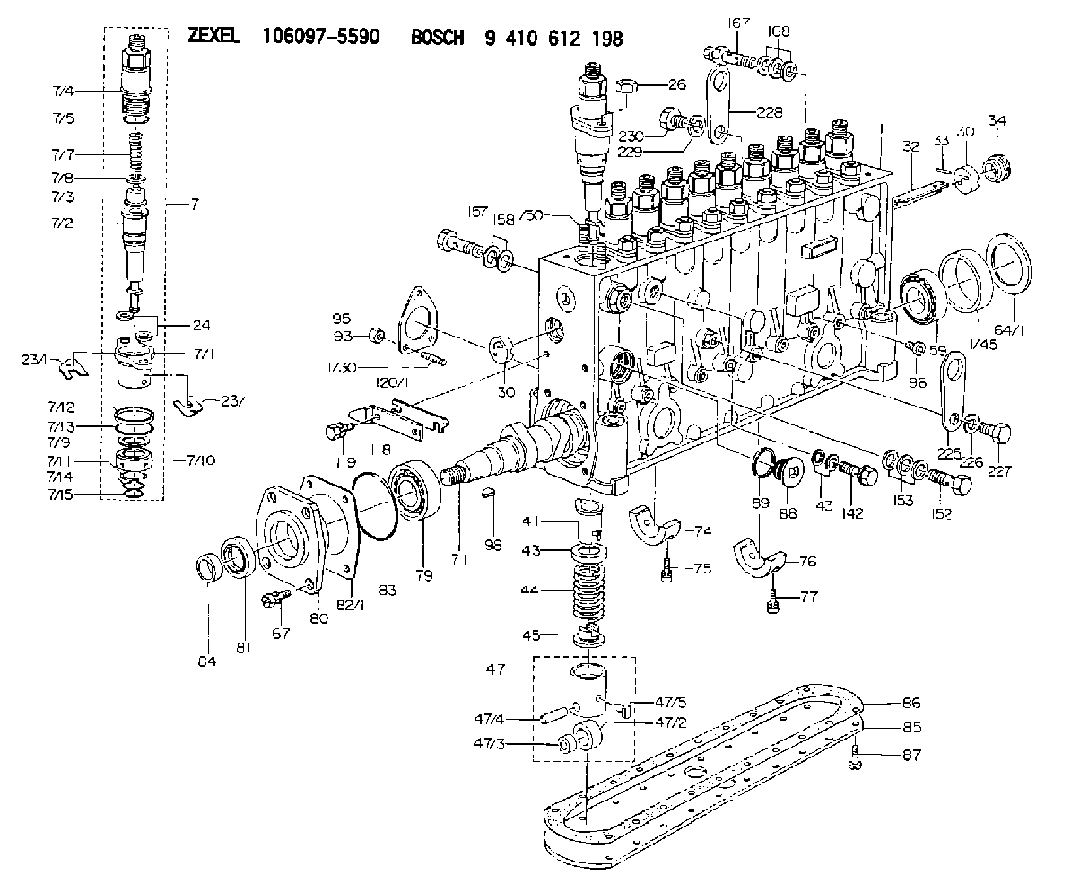
| 1. | [1] | 134066-0220 | PUMP HOUSING |
| 1/30. | [3] | 029040-6020 | STUD |
| 1/45. | [1] | 134311-0000 | SPACER RING |
| 1/50. | [20] | 134138-0000 | STUD |
| 7. | [10] | 134146-7620 | PLUNGER-AND-BARREL ASSY |
| 7/1. | [10] | 134131-1020 | FLANGE BUSHING |
| 7/2. | [10] | 134152-3420 | PLUNGER-AND-BARREL ASSY |
| 7/3. | [10] | 134160-0320 | DELIVERY-VALVE ASSEMBLY |
| 7/4. | [10] | 134116-3521 | FITTING |
| 7/5. | [10] | 029632-2070 | O-RING |
| 7/7. | [10] | 134112-2300 | COMPRESSION SPRING |
| 7/8. | [10] | 134115-0100 | GASKET |
| 7/9. | [10] | 029302-0140 | PLAIN WASHER |
| 7/10. | [10] | 134135-0200 | CAPSULE |
| 7/11. | [10] | 029602-0010 | LOCKING WASHER |
| 7/12. | [10] | 134137-0100 | SPACER RING |
| 7/13. | [10] | 029632-9030 | O-RING |
| 7/14. | [10] | 029631-5020 | O-RING |
| 7/15. | [10] | 029631-5020 | O-RING |
| 23/1. | [0] | 139400-0900 | SHIM T0.500 |
| 23/1. | [0] | 139400-1000 | SHIM T0.525 |
| 23/1. | [0] | 139400-1100 | SHIM T0.550 |
| 23/1. | [0] | 139400-1200 | SHIM T0.575 |
| 23/1. | [0] | 139400-1300 | SHIM T0.600 |
| 23/1. | [0] | 139400-1400 | SHIM T0.625 |
| 23/1. | [0] | 139400-1500 | SHIM T0.650 |
| 23/1. | [0] | 139400-1600 | SHIM T0.675 |
| 23/1. | [0] | 139400-1700 | SHIM T0.700 |
| 23/1. | [0] | 139400-1800 | SHIM T0.725 |
| 23/1. | [0] | 139400-1900 | SHIM T0.750 |
| 23/1. | [0] | 139400-2000 | SHIM T0.775 |
| 23/1. | [0] | 139400-2100 | SHIM T0.800 |
| 23/1. | [0] | 139400-2200 | SHIM T0.825 |
| 23/1. | [0] | 139400-2300 | SHIM T0.850 |
| 23/1. | [0] | 139400-2400 | SHIM T0.875 |
| 23/1. | [0] | 139400-2500 | SHIM T0.900 |
| 23/1. | [0] | 139400-2600 | SHIM T0.925 |
| 23/1. | [0] | 139400-2700 | SHIM T0.950 |
| 23/1. | [0] | 139400-2800 | SHIM T0.975 |
| 23/1. | [0] | 139400-2900 | SHIM T1.000 |
| 23/1. | [0] | 139400-3000 | SHIM T1.025 |
| 23/1. | [0] | 139400-3100 | SHIM T1.050 |
| 23/1. | [0] | 139400-3200 | SHIM T1.075 |
| 23/1. | [0] | 139400-3300 | SHIM T1.100 |
| 23/1. | [0] | 139400-3400 | SHIM T1.125 |
| 23/1. | [0] | 139400-3500 | SHIM T1.150 |
| 23/1. | [0] | 139400-3600 | SHIM T1.175 |
| 23/1. | [0] | 139400-3600 | SHIM T1.175 |
| 23/1. | [0] | 139400-3700 | SHIM T1.200 |
| 23/1. | [0] | 139400-3800 | SHIM T1.225 |
| 23/1. | [0] | 139400-3900 | SHIM T1.250 |
| 23/1. | [0] | 139400-4000 | SHIM T1.275 |
| 23/1. | [0] | 139400-4100 | SHIM T1.300 |
| 23/1. | [0] | 139400-4200 | SHIM T1.325 |
| 23/1. | [0] | 139400-4300 | SHIM T1.350 |
| 23/1. | [0] | 139400-4400 | SHIM T1.375 |
| 23/1. | [0] | 139400-4500 | SHIM T1.400 |
| 23/1. | [0] | 139400-4600 | SHIM T1.425 |
| 23/1. | [0] | 139400-4700 | SHIM T1.450 |
| 23/1. | [0] | 139400-4800 | SHIM T1.475 |
| 23/1. | [0] | 139400-4900 | SHIM T1.500 |
| 23/1. | [0] | 139400-5000 | SHIM T1.525 |
| 23/1. | [0] | 139400-5100 | SHIM T1.550 |
| 23/1. | [0] | 139400-5200 | SHIM T1.575 |
| 23/1. | [0] | 139400-5300 | SHIM T1.600 |
| 23/1. | [0] | 139400-5400 | SHIM T1.625 |
| 23/1. | [0] | 139400-5500 | SHIM T1.650 |
| 23/1. | [0] | 139400-5600 | SHIM T1.675 |
| 23/1. | [0] | 139400-5700 | SHIM T1.700 |
| 23/1. | [0] | 139400-5800 | SHIM T1.725 |
| 23/1. | [0] | 139400-5900 | SHIM T1.750 |
| 23/1. | [0] | 139400-6000 | SHIM T1.775 |
| 23/1. | [0] | 139400-6100 | SHIM T1.800 |
| 23/1. | [0] | 139400-6200 | SHIM T1.825 |
| 23/1. | [0] | 139400-6300 | SHIM T1.850 |
| 23/1. | [0] | 139400-6400 | SHIM T1.875 |
| 23/1. | [0] | 139400-6500 | SHIM T1.900 |
| 23/1. | [0] | 139400-6600 | SHIM T1.925 |
| 23/1. | [0] | 139400-6700 | SHIM T1.950 |
| 23/1. | [0] | 139400-6800 | SHIM T1.975 |
| 24. | [20] | 134132-0300 | PLAIN WASHER D20&11T2.5 |
| 26. | [20] | 013021-0040 | UNION NUT M10P1.5H8 |
| 30. | [2] | 134001-0000 | BUSHING |
| 30. | [2] | 134001-0000 | BUSHING |
| 32. | [1] | 134250-0000 | CONTROL RACK |
| 33. | [1] | 024030-2030 | BEARING PIN |
| 34. | [1] | 134222-0000 | BUSHING |
| 41. | [10] | 134241-0320 | CONTROL SLEEVE |
| 43. | [10] | 134216-0000 | SLOTTED WASHER |
| 44. | [10] | 134215-0700 | COILED SPRING |
| 45. | [10] | 134217-0500 | SLOTTED WASHER |
| 47. | [10] | 134200-0420 | TAPPET |
| 47/2. | [1] | 134204-0100 | ROLLER |
| 47/3. | [1] | 134205-0000 | BUSHING |
| 47/4. | [1] | 134203-0000 | BEARING PIN |
| 47/5. | [1] | 131206-0500 | SLIDER |
| 59. | [1] | 016650-2230 | BEARING PLATE |
| 64/1. | [0] | 134303-0000 | SHIM D59.8&43T1.2 |
| 64/1. | [0] | 134303-0100 | SHIM D59.8&43T1.5 |
| 64/1. | [0] | 134303-0200 | SHIM D59.8&43T1.8 |
| 64/1. | [0] | 134303-0300 | SHIM D59.8&43T2.0 |
| 64/1. | [0] | 134303-0400 | SHIM D59.8&43T0.6 |
| 67. | [4] | 029010-6810 | BLEEDER SCREW |
| 71. | [1] | 134391-1600 | CAMSHAFT |
| 74. | [2] | 134306-0600 | BEARING SHELL |
| 75. | [4] | 020106-2040 | BLEEDER SCREW M6P1L20 |
| 76. | [2] | 134306-1200 | BEARING SHELL |
| 77. | [4] | 020106-2040 | BLEEDER SCREW M6P1L20 |
| 79. | [1] | 016650-2230 | BEARING PLATE |
| 80. | [1] | 134316-1700 | COVER |
| 81. | [1] | 139625-0000 | PACKING RING |
| 82/1. | [0] | 134314-0000 | SHIM T0.1 |
| 82/1. | [0] | 134314-0100 | SHIM T0.12 |
| 82/1. | [0] | 134314-0200 | SHIM T0.14 |
| 82/1. | [0] | 134314-0300 | SHIM T0.16 |
| 82/1. | [0] | 134314-0400 | SHIM T0.18 |
| 82/1. | [0] | 134314-0500 | SHIM T0.3 |
| 82/1. | [0] | 134314-0600 | SHIM T0.5 |
| 83. | [1] | 029635-5010 | O-RING |
| 84. | [1] | 134563-0900 | SLIDING PIECE |
| 85. | [1] | 134043-0300 | COVER |
| 86. | [1] | 134042-1600 | GASKET |
| 87. | [16] | 012206-1640 | FLAT-HEAD SCREW M6P1L16 |
| 88. | [1] | 134045-0100 | CAPSULE |
| 89. | [1] | 026524-2940 | GASKET D28.9&24.3T2 |
| 93. | [3] | 139206-0400 | UNION NUT |
| 95. | [1] | 131041-0800 | GASKET |
| 96. | [10] | 134047-0000 | CAPSULE |
| 98. | [1] | 025805-1910 | WOODRUFF KEY |
| 118. | [1] | 134496-4900 | POINTER |
| 119. | [2] | 029020-6210 | BLEEDER SCREW |
| 120/1. | [0] | 139400-0100 | SHIM T0.2 |
| 120/1. | [0] | 139400-0200 | SHIM T0.3 |
| 120/1. | [0] | 139400-0300 | SHIM T0.5 |
| 120/1. | [0] | 139400-0400 | SHIM T1.0 |
| 120/1. | [0] | 139400-7200 | SHIM T0.1 |
| 142. | [1] | 134430-0200 | EYE BOLT |
| 143. | [2] | 139510-0300 | GASKET |
| 152. | [1] | 139814-0400 | EYE BOLT |
| 153. | [3] | 139514-0300 | GASKET |
| 157. | [1] | 029731-4680 | EYE BOLT |
| 158. | [2] | 139514-0300 | GASKET |
| 167. | [1] | 134424-0820 | OVER FLOW VALVE |
| 168. | [3] | 139514-0300 | GASKET |
| 225. | [1] | 134510-4700 | HANGER |
| 226. | [1] | 014111-4440 | LOCKING WASHER |
| 227. | [1] | 134510-4800 | BLEEDER SCREW |
| 228. | [1] | 134510-4700 | HANGER |
| 229. | [1] | 014111-4440 | LOCKING WASHER |
| 230. | [1] | 134510-4800 | BLEEDER SCREW |
Cross reference number
Zexel num
Bosch num
Firm num
Name
106097-5590
9 410 612 198
221003450A HINO
FUEL-INJECTION PUMP
* Q
* Q
Information:
Repair
Measure crankshaft main journal to main bearing clearance.
Fig. 5-Main Bearing ClearanceMain bearing journal O.D. (new) (1, Fig. 5) ... 3.123 to 3.124 inch(79.32 to 79.35 mm)Assembled Main bearing I.D. (new) (2) ... 3.126 to 3.128 inch(79.39 to 79.45 mm)Main bearing clearance (new) (3) ... 0.0016 to 0.0046 inch(0.041 to 0.117 mm)Main bearing clearance (maximum) ... 0.006 inch(0.15 mm)Main bearing bore I.D. (4) ... 3.325 to 3.326 inch(84.46 to 84.48 mm)Measure crankshaft main journal taper and roundness.
Fig. 6-Main Bearing MeasurementJournal taper (maximum) (1, Fig. 6) ... 0.001 inch per 1.00 inch(0.03 mm per 25.4 mm)Journal out-of-round (maximum) (2, Fig. 6) ... 0.003 inch(0.08 mm)If wear is even, but out of specifications, dress crankshaft main journals and select proper undersize bearing inserts.If journals are out-of-round or tapered, grind crankshaft and select proper undersize bearing inserts.If crankshaft end play is excessive, replace worn thrust bearings or grind crankshaft thrust surfaces and select proper oversize thrust bearing.Installation
Fig. 7-Main Bearing Insert InstallationPosition bearing inserts in cylinder block and main bearing caps with the tang on the insert engaged in the slot in the cylinder block and main bearing caps (Fig. 7).Apply a coat of clean engine oil to the bearing surface of the inserts.Position crankshaft in cylinder block. Tangs on main bearing halves in main bearing caps must be positioned to the same side of the crankshaft as the tangs on main bearing halves in cylinder block.
Fig. 8-Main Bearing Cap PositionsInstall main bearing caps with numbers (1, Fig. 8) corresponding to numbers in oil pan rail (2). If there is no arrow (3) machined on main bearing cap, install cap with number to same side as numbers in oil pan rail. If there is an arrow machined on main bearing cap, arrow must point toward camshaft side.Dip main bearing cap screws in clean engine oil and position them in the main bearing caps. IMPORTANT: Do not use pneumatic wrench to install main bearing cap screws.Before tightening cap screws on main bearing caps, align upper and lower thrust flanges on main thrust bearings. Using a soft-face hammer, tap crankshaft to the rear and then to the front to line up thrust bearing flanges.Rotate crankshaft by hand. Crankshaft should rotate with little effort.
Fig. 9-Main Bearing Cap ScrewTighten main bearing cap screws (Fig. 9)Main bearing cap screw torque ... 85 lb-ft(115 N m) (12 kg-m)Turn crankshaft by hand. If it does not turn easily, disassemble parts and determine the cause.Pull piston and connecting rods into position against the crankshaft.Install connecting rod caps (Group 0403).Install engine front plate (Group 0404).Install camshaft (Group 0402).Install timing gear train (Group 0402).Install timing gear cover (Group 0402).Install vibration damper (Group 0401).Install fan belt and alternator belt (Group 0429).Install flywheel housing (Group 0433).Install flywheel (Group 0433).Install oil pan (Group 0407).Install pushrods and rocker arm assembly (Group 0402).Install rocker arm cover (Group 0402).Install fuel transfer pump (Group 0421).Crankshaft Gear
Removal
Remove crankshaft from engine (Group 0401).
Fig. 10-Crankshaft Gear RemovalUse knife-edge puller (1, Fig. 10) to remove crankshaft gear (2) from
Have questions with 106097-5590?
Group cross 106097-5590 ZEXEL
Nissan-Diesel
Nissan-Diesel
Mitsubishi
Nissan-Diesel
Nissan-Diesel
Mitsubishi
Hino
106097-5590
9 410 612 198
221003450A
FUEL-INJECTION PUMP