Information fuel-injection pump
BOSCH
9 410 614 322
9410614322
ZEXEL
106096-9333
1060969333
Rating:
Scheme ###:
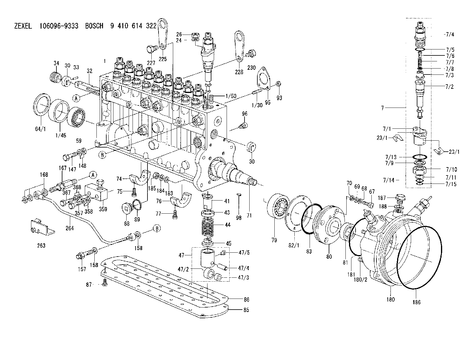
| 1. | [1] | 134056-0120 | PUMP HOUSING |
| 1/30. | [3] | 029040-6020 | STUD |
| 1/45. | [1] | 134311-0000 | SPACER RING |
| 1/50. | [20] | 134138-0000 | STUD |
| 7. | [10] | 134143-2921 | PLUNGER-AND-BARREL ASSY |
| 7/1. | [1] | 134131-1920 | FLANGE BUSHING |
| 7/2. | [1] | 134101-9120 | PLUNGER-AND-BARREL ASSY |
| 7/3. | [1] | 134110-4220 | DELIVERY-VALVE ASSEMBLY |
| 7/4. | [1] | 134116-4400 | FITTING |
| 7/5. | [1] | 139722-0400 | O-RING |
| 7/6. | [1] | 131117-2100 | FILLER PIECE |
| 7/7. | [1] | 131112-2300 | COILED SPRING |
| 7/8. | [1] | 134115-0100 | GASKET |
| 7/9. | [1] | 029302-0140 | PLAIN WASHER |
| 7/10. | [1] | 134135-0400 | CAPSULE |
| 7/11. | [1] | 029602-0010 | LOCKING WASHER |
| 7/13. | [1] | 139729-0400 | O-RING |
| 7/14. | [1] | 139715-0400 | O-RING |
| 7/15. | [1] | 139715-0400 | O-RING |
| 23/1. | [0] | 139400-0900 | SHIM T0.500 |
| 23/1. | [0] | 139400-1000 | SHIM T0.525 |
| 23/1. | [0] | 139400-1100 | SHIM T0.550 |
| 23/1. | [0] | 139400-1200 | SHIM T0.575 |
| 23/1. | [0] | 139400-1300 | SHIM T0.600 |
| 23/1. | [0] | 139400-1400 | SHIM T0.625 |
| 23/1. | [0] | 139400-1500 | SHIM T0.650 |
| 23/1. | [0] | 139400-1600 | SHIM T0.675 |
| 23/1. | [0] | 139400-1700 | SHIM T0.700 |
| 23/1. | [0] | 139400-1800 | SHIM T0.725 |
| 23/1. | [0] | 139400-1900 | SHIM T0.750 |
| 23/1. | [0] | 139400-2000 | SHIM T0.775 |
| 23/1. | [0] | 139400-2100 | SHIM T0.800 |
| 23/1. | [0] | 139400-2200 | SHIM T0.825 |
| 23/1. | [0] | 139400-2300 | SHIM T0.850 |
| 23/1. | [0] | 139400-2400 | SHIM T0.875 |
| 23/1. | [0] | 139400-2500 | SHIM T0.900 |
| 23/1. | [0] | 139400-2600 | SHIM T0.925 |
| 23/1. | [0] | 139400-2700 | SHIM T0.950 |
| 23/1. | [0] | 139400-2800 | SHIM T0.975 |
| 23/1. | [0] | 139400-2900 | SHIM T1.000 |
| 23/1. | [0] | 139400-3000 | SHIM T1.025 |
| 23/1. | [0] | 139400-3100 | SHIM T1.050 |
| 23/1. | [0] | 139400-3200 | SHIM T1.075 |
| 23/1. | [0] | 139400-3300 | SHIM T1.100 |
| 23/1. | [0] | 139400-3400 | SHIM T1.125 |
| 23/1. | [0] | 139400-3500 | SHIM T1.150 |
| 23/1. | [0] | 139400-3600 | SHIM T1.175 |
| 23/1. | [0] | 139400-3700 | SHIM T1.200 |
| 23/1. | [0] | 139400-3800 | SHIM T1.225 |
| 23/1. | [0] | 139400-3900 | SHIM T1.250 |
| 23/1. | [0] | 139400-4000 | SHIM T1.275 |
| 23/1. | [0] | 139400-4100 | SHIM T1.300 |
| 23/1. | [0] | 139400-4200 | SHIM T1.325 |
| 23/1. | [0] | 139400-4300 | SHIM T1.350 |
| 23/1. | [0] | 139400-4400 | SHIM T1.375 |
| 23/1. | [0] | 139400-4500 | SHIM T1.400 |
| 23/1. | [0] | 139400-4600 | SHIM T1.425 |
| 23/1. | [0] | 139400-4700 | SHIM T1.450 |
| 23/1. | [0] | 139400-4800 | SHIM T1.475 |
| 23/1. | [0] | 139400-4900 | SHIM T1.500 |
| 23/1. | [0] | 139400-5000 | SHIM T1.525 |
| 23/1. | [0] | 139400-5100 | SHIM T1.550 |
| 23/1. | [0] | 139400-5200 | SHIM T1.575 |
| 23/1. | [0] | 139400-5300 | SHIM T1.600 |
| 23/1. | [0] | 139400-5400 | SHIM T1.625 |
| 23/1. | [0] | 139400-5500 | SHIM T1.650 |
| 23/1. | [0] | 139400-5600 | SHIM T1.675 |
| 23/1. | [0] | 139400-5700 | SHIM T1.700 |
| 23/1. | [0] | 139400-5800 | SHIM T1.725 |
| 23/1. | [0] | 139400-5900 | SHIM T1.750 |
| 23/1. | [0] | 139400-6000 | SHIM T1.775 |
| 23/1. | [0] | 139400-6100 | SHIM T1.800 |
| 23/1. | [0] | 139400-6200 | SHIM T1.825 |
| 23/1. | [0] | 139400-6300 | SHIM T1.850 |
| 23/1. | [0] | 139400-6400 | SHIM T1.875 |
| 23/1. | [0] | 139400-6500 | SHIM T1.900 |
| 23/1. | [0] | 139400-6600 | SHIM T1.925 |
| 23/1. | [0] | 139400-6700 | SHIM T1.950 |
| 23/1. | [0] | 139400-6700 | SHIM T1.950 |
| 23/1. | [0] | 139400-6800 | SHIM T1.975 |
| 24. | [20] | 134132-0300 | PLAIN WASHER D20&11T2.5 |
| 26. | [20] | 013021-0040 | UNION NUT M10P1.5H8 |
| 30. | [2] | 134001-0000 | BUSHING |
| 30. | [2] | 134001-0000 | BUSHING |
| 32. | [1] | 134250-0800 | CONTROL RACK |
| 33. | [1] | 024030-2030 | BEARING PIN |
| 34. | [1] | 134222-0000 | BUSHING |
| 41. | [10] | 134241-0021 | CONTROL SLEEVE |
| 43. | [10] | 134216-0000 | SLOTTED WASHER |
| 44. | [10] | 134215-0400 | COMPRESSION SPRING |
| 45. | [10] | 134217-0500 | SLOTTED WASHER |
| 47. | [10] | 134200-0020 | TAPPET |
| 47/2. | [1] | 134204-0000 | ROLLER |
| 47/3. | [1] | 134205-0000 | BUSHING |
| 47/4. | [1] | 134203-0000 | BEARING PIN |
| 47/5. | [1] | 131206-0500 | SLIDER |
| 59. | [1] | 016650-2230 | BEARING PLATE |
| 64/1. | [0] | 134303-0000 | SHIM D59.8&43T1.2 |
| 64/1. | [0] | 134303-0100 | SHIM D59.8&43T1.5 |
| 64/1. | [0] | 134303-0200 | SHIM D59.8&43T1.8 |
| 64/1. | [0] | 134303-0300 | SHIM D59.8&43T2.0 |
| 64/1. | [0] | 134303-0400 | SHIM D59.8&43T0.6 |
| 67. | [4] | 134329-0000 | BLEEDER SCREW |
| 68. | [4] | 029320-6010 | LOCKING WASHER |
| 69. | [4] | 029300-6170 | SHIM D12&6.2T1 |
| 70. | [4] | 029340-6120 | GASKET |
| 71. | [1] | 134391-0900 | CAMSHAFT |
| 74. | [2] | 134306-0500 | BEARING SHELL |
| 75. | [4] | 020106-2040 | BLEEDER SCREW M6P1L20 |
| 76. | [1] | 134306-0400 | BEARING SHELL |
| 77. | [2] | 020106-2040 | BLEEDER SCREW M6P1L20 |
| 79. | [1] | 016650-2230 | BEARING PLATE |
| 80. | [1] | 134316-2400 | COVER |
| 81. | [1] | 026712-5010 | PACKING RING |
| 82/1. | [0] | 134314-0000 | SHIM T0.1 |
| 82/1. | [0] | 134314-0100 | SHIM T0.12 |
| 82/1. | [0] | 134314-0200 | SHIM T0.14 |
| 82/1. | [0] | 134314-0300 | SHIM T0.16 |
| 82/1. | [0] | 134314-0400 | SHIM T0.18 |
| 82/1. | [0] | 134314-0500 | SHIM T0.3 |
| 82/1. | [0] | 134314-0600 | SHIM T0.5 |
| 83. | [1] | 029635-5010 | O-RING |
| 85. | [1] | 134043-1400 | COVER |
| 86. | [1] | 134042-1600 | GASKET |
| 87. | [16] | 012206-1640 | FLAT-HEAD SCREW M6P1L16 |
| 88. | [1] | 134045-0100 | CAPSULE |
| 89. | [1] | 026524-2940 | GASKET D28.9&24.3T2 |
| 93. | [3] | 139206-0400 | UNION NUT |
| 95. | [1] | 131041-0800 | GASKET |
| 96. | [10] | 134047-0000 | CAPSULE |
| 98. | [1] | 025805-1910 | WOODRUFF KEY |
| 147. | [1] | 139810-0000 | EYE BOLT |
| 148. | [2] | 139510-0000 | GASKET D15.2&10.2T1.0 |
| 157. | [1] | 134424-3520 | OVER FLOW VALVE |
| 158. | [2] | 139514-0000 | GASKET D19.2&14.2T1.0 |
| 158. | [2] | 139514-0000 | GASKET D19.2&14.2T1.0 |
| 167. | [1] | 134424-2720 | OVER FLOW VALVE |
| 168. | [3] | 139514-0000 | GASKET D19.2&14.2T1.0 |
| 180. | [1] | 134459-0420 | BRACKET |
| 180/2. | [4] | 029041-0300 | STUD |
| 181. | [1] | 139789-0100 | O-RING |
| 183. | [4] | 014011-0140 | PLAIN WASHER D22&10.5T1.6 |
| 184. | [4] | 014111-0440 | LOCKING WASHER |
| 185. | [4] | 013021-0040 | UNION NUT M10P1.5H8 |
| 186. | [1] | 139799-0500 | O-RING |
| 187. | [1] | 139926-0000 | CAPSULE |
| 188. | [1] | 026526-3140 | GASKET D30.9&26.3T2 |
| 225. | [1] | 131439-0300 | HANGER |
| 227. | [1] | 131329-0300 | BLEEDER SCREW |
| 228. | [1] | 131439-0300 | HANGER |
| 230. | [1] | 131329-0300 | BLEEDER SCREW |
| 263. | [1] | 134510-9720 | BRACKET |
| 264. | [1] | 134442-1020 | PIPE |
| 357. | [1] | 139814-1000 | EYE BOLT |
| 358. | [2] | 139514-0000 | GASKET D19.2&14.2T1.0 |
| 359. | [1] | 134442-2220 | CONNECTOR |
| 367. | [1] | 139814-1000 | EYE BOLT |
| 368. | [2] | 139514-0000 | GASKET D19.2&14.2T1.0 |
Include in #1:
106961-6210
as FUEL INJECTION PUMP
Cross reference number
Zexel num
Bosch num
Firm num
Name
106096-9333
9 410 614 322
FUEL-INJECTION PUMP
* Q
* Q
Information:
Maintenance
Every 20,000 miles (30,000 km) or 1,000 hours, clean the oil drain pipe from turbocharger to sump, also turbocharger compressor wheel and cover.
T1Remove the air inlet duct and compressor housing and check for dirt or dust build-up (see Fig. T.1).Remove all foreign matter - determine and correct cause of build up.Use soft brush on compressor wheel as uneven deposits can affect rotor balance and cause bearing failure.With the compressor housing removed, push the compressor wheel towards the turbine wheel and turn rotating assembly by hand: check for binding and rubbing. Listen carefully for unusual noises. If binding or rubbing is evident, remove the turbocharger for dismantling and inspection.To Remove Turbocharger
Disconnect turbocharger inlet and outlet connections.Disconnect exhaust pipe.Remove oil supply pipe and release oil drain pipe.Release turbocharger outlet assembly from the cylinder block.
T2Remove turbocharger from exhaust manifold, (see Fig. T.2).Seal open engine connections.Airesearch T-31 (see Fig. T.3)
T3Dismantling
Clean the exterior with a pressure spray of a non-caustic cleaning solvent before dismantling. Dismantle only as required to make necessary inspection or repairs. Note: The 'Wastegate' unit where fitted, cannot be dismantled. See page T.4 for service/calibration instructions. As each part is removed, place in a clean container to prevent loss or damage.Remove the bolts, clamps and lockplates which hold the compressor and turbine housings to the centre housing group. Tap the housings with a soft faced hammer if force is needed for removal. Exercise caution when removing housings to prevent damage to compressor or turbine wheel. Once damaged, they cannot be repaired. Never attempt to straighten bent compressor or turbine blades-replace the faulty component.Place the centre housing group in a suitable holding fixture which will prevent the turbine wheel from turning.Use a T-handled wrench when removing the compressor wheel locknut to avoid possible bending of the shaft.Lift the compressor wheel off the shaft. Remove the shaft wheel from the centre housing keeping shaft central with bearings until clear of centre housing. The turbine wheel shroud is not retained to the centre housing and will fall free when the shaft wheel is removed.Remove lockplates and bolts from back plate.Tap backplate with soft mallet to remove from recess in centre housing.Remove thrust collar and thrust bearing from centre housing.Remove bearings and retainers from centre housing. Discard rubber sealing ring.Cleaning
Before cleaning, inspect all parts for signs of rubbing, burning or other damage which might not be evident after cleaning.Soak all parts in clean non-caustic carbon solvent. After soaking, use a stiff bristle brush and remove all dirt particles. Dry parts thoroughly. Normally a light accumulation of carbon deposits will not affect turbine operation.Internal Parts Inspection (see Fig. T.4)
T4Parts must now show signs of damage, corrosion or deterioration. Threads must not be nicked, crossed or stripped.The turbine wheel must show no signs of rubbing and vanes must not be torn or worn to a feather edge. The shaft must show little signs of scoring, scratches or seizure with the bearings.The compressor must show no signs of rubbing or damage from foreign matter. The compressor wheel
Have questions with 106096-9333?
Group cross 106096-9333 ZEXEL
Isuzu
Isuzu
106096-9333
9 410 614 322
FUEL-INJECTION PUMP