Information fuel-injection pump
BOSCH
9 410 613 026
9410613026
ZEXEL
106087-5402
1060875402
Rating:
Scheme ###:
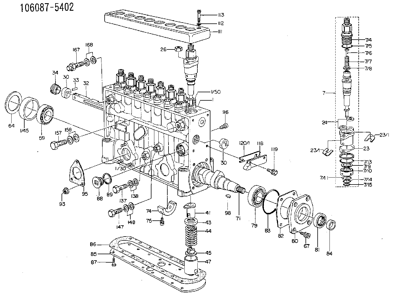
| 1. | [1] | 134050-5521 | PUMP HOUSING |
| 1/30. | [3] | 029040-6020 | STUD |
| 1/45. | [1] | 134311-0000 | SPACER RING |
| 1/50. | [16] | 134138-0000 | STUD |
| 7. | [8] | 134143-6120 | PLUNGER-AND-BARREL ASSY |
| 7/1. | [8] | 134131-1020 | FLANGE BUSHING |
| 7/2. | [8] | 134151-0420 | PLUNGER-AND-BARREL ASSY |
| 7/3. | [8] | 134110-5420 | DELIVERY-VALVE ASSEMBLY |
| 7/4. | [8] | 134116-3200 | FITTING |
| 7/5. | [8] | 029632-2070 | O-RING |
| 7/6. | [8] | 134117-1400 | FILLER PIECE |
| 7/7. | [8] | 134112-0600 | COILED SPRING |
| 7/8. | [8] | 134115-0100 | GASKET |
| 7/9. | [8] | 029302-0140 | PLAIN WASHER |
| 7/10. | [8] | 134135-0200 | CAPSULE |
| 7/11. | [8] | 029602-0010 | LOCKING WASHER |
| 7/12. | [8] | 134137-0100 | SPACER RING |
| 7/13. | [8] | 029632-9030 | O-RING |
| 7/14. | [8] | 029631-5020 | O-RING |
| 7/15. | [8] | 029631-5020 | O-RING |
| 23/1. | [0] | 139400-0900 | SHIM T0.500 |
| 23/1. | [0] | 139400-0900 | SHIM T0.500 |
| 23/1. | [0] | 139400-1000 | SHIM T0.525 |
| 23/1. | [0] | 139400-1100 | SHIM T0.550 |
| 23/1. | [0] | 139400-1200 | SHIM T0.575 |
| 23/1. | [0] | 139400-1300 | SHIM T0.600 |
| 23/1. | [0] | 139400-1400 | SHIM T0.625 |
| 23/1. | [0] | 139400-1500 | SHIM T0.650 |
| 23/1. | [0] | 139400-1600 | SHIM T0.675 |
| 23/1. | [0] | 139400-1700 | SHIM T0.700 |
| 23/1. | [0] | 139400-1800 | SHIM T0.725 |
| 23/1. | [0] | 139400-1900 | SHIM T0.750 |
| 23/1. | [0] | 139400-2000 | SHIM T0.775 |
| 23/1. | [0] | 139400-2100 | SHIM T0.800 |
| 23/1. | [0] | 139400-2200 | SHIM T0.825 |
| 23/1. | [0] | 139400-2300 | SHIM T0.850 |
| 23/1. | [0] | 139400-2400 | SHIM T0.875 |
| 23/1. | [0] | 139400-2500 | SHIM T0.900 |
| 23/1. | [0] | 139400-2600 | SHIM T0.925 |
| 23/1. | [0] | 139400-2700 | SHIM T0.950 |
| 23/1. | [0] | 139400-2800 | SHIM T0.975 |
| 23/1. | [0] | 139400-2900 | SHIM T1.000 |
| 23/1. | [0] | 139400-3000 | SHIM T1.025 |
| 23/1. | [0] | 139400-3100 | SHIM T1.050 |
| 23/1. | [0] | 139400-3200 | SHIM T1.075 |
| 23/1. | [0] | 139400-3300 | SHIM T1.100 |
| 23/1. | [0] | 139400-3400 | SHIM T1.125 |
| 23/1. | [0] | 139400-3500 | SHIM T1.150 |
| 23/1. | [0] | 139400-3600 | SHIM T1.175 |
| 23/1. | [0] | 139400-3700 | SHIM T1.200 |
| 23/1. | [0] | 139400-3800 | SHIM T1.225 |
| 23/1. | [0] | 139400-3900 | SHIM T1.250 |
| 23/1. | [0] | 139400-4000 | SHIM T1.275 |
| 23/1. | [0] | 139400-4100 | SHIM T1.300 |
| 23/1. | [0] | 139400-4200 | SHIM T1.325 |
| 23/1. | [0] | 139400-4300 | SHIM T1.350 |
| 23/1. | [0] | 139400-4400 | SHIM T1.375 |
| 23/1. | [0] | 139400-4500 | SHIM T1.400 |
| 23/1. | [0] | 139400-4600 | SHIM T1.425 |
| 23/1. | [0] | 139400-4700 | SHIM T1.450 |
| 23/1. | [0] | 139400-4800 | SHIM T1.475 |
| 23/1. | [0] | 139400-4900 | SHIM T1.500 |
| 23/1. | [0] | 139400-5000 | SHIM T1.525 |
| 23/1. | [0] | 139400-5100 | SHIM T1.550 |
| 23/1. | [0] | 139400-5200 | SHIM T1.575 |
| 23/1. | [0] | 139400-5300 | SHIM T1.600 |
| 23/1. | [0] | 139400-5400 | SHIM T1.625 |
| 23/1. | [0] | 139400-5500 | SHIM T1.650 |
| 23/1. | [0] | 139400-5600 | SHIM T1.675 |
| 23/1. | [0] | 139400-5700 | SHIM T1.700 |
| 23/1. | [0] | 139400-5800 | SHIM T1.725 |
| 23/1. | [0] | 139400-5900 | SHIM T1.750 |
| 23/1. | [0] | 139400-6000 | SHIM T1.775 |
| 23/1. | [0] | 139400-6100 | SHIM T1.800 |
| 23/1. | [0] | 139400-6200 | SHIM T1.825 |
| 23/1. | [0] | 139400-6300 | SHIM T1.850 |
| 23/1. | [0] | 139400-6400 | SHIM T1.875 |
| 23/1. | [0] | 139400-6500 | SHIM T1.900 |
| 23/1. | [0] | 139400-6600 | SHIM T1.925 |
| 23/1. | [0] | 139400-6700 | SHIM T1.950 |
| 23/1. | [0] | 139400-6800 | SHIM T1.975 |
| 24. | [16] | 134132-0300 | PLAIN WASHER D20&11T2.5 |
| 26. | [16] | 013021-0040 | UNION NUT M10P1.5H8 |
| 30. | [2] | 134001-0000 | BUSHING |
| 30. | [2] | 134001-0000 | BUSHING |
| 32. | [1] | 134258-0000 | CONTROL RACK |
| 33. | [1] | 024030-2030 | BEARING PIN |
| 34. | [1] | 134222-0000 | BUSHING |
| 41. | [8] | 134241-0021 | CONTROL SLEEVE |
| 43. | [8] | 134216-0000 | SLOTTED WASHER |
| 44. | [8] | 134215-0300 | COMPRESSION SPRING |
| 45. | [8] | 134217-0500 | SLOTTED WASHER |
| 47. | [8] | 134200-0020 | TAPPET |
| 47/2. | [1] | 134204-0000 | ROLLER |
| 47/3. | [1] | 134205-0000 | BUSHING |
| 47/4. | [1] | 134203-0000 | BEARING PIN |
| 47/5. | [1] | 131206-0500 | SLIDER |
| 59. | [1] | 016650-2230 | BEARING PLATE |
| 64/1. | [0] | 134303-0000 | SHIM D59.8&43T1.2 |
| 64/1. | [0] | 134303-0100 | SHIM D59.8&43T1.5 |
| 64/1. | [0] | 134303-0200 | SHIM D59.8&43T1.8 |
| 64/1. | [0] | 134303-0300 | SHIM D59.8&43T2.0 |
| 64/1. | [0] | 134303-0400 | SHIM D59.8&43T0.6 |
| 67. | [4] | 029010-6810 | BLEEDER SCREW |
| 71. | [1] | 134381-0700 | CAMSHAFT |
| 74. | [1] | 134306-0000 | BEARING SHELL |
| 75. | [2] | 020106-2040 | BLEEDER SCREW M6P1L20 |
| 79. | [1] | 016650-2230 | BEARING PLATE |
| 80. | [1] | 134316-0100 | COVER |
| 81. | [1] | 026712-5010 | PACKING RING |
| 82/1. | [0] | 134314-0000 | SHIM T0.1 |
| 82/1. | [0] | 134314-0100 | SHIM T0.12 |
| 82/1. | [0] | 134314-0200 | SHIM T0.14 |
| 82/1. | [0] | 134314-0300 | SHIM T0.16 |
| 82/1. | [0] | 134314-0400 | SHIM T0.18 |
| 82/1. | [0] | 134314-0500 | SHIM T0.3 |
| 82/1. | [0] | 134314-0600 | SHIM T0.5 |
| 83. | [1] | 029635-5010 | O-RING |
| 85. | [1] | 134043-0700 | COVER |
| 86. | [1] | 134042-1500 | GASKET |
| 87. | [14] | 012206-1640 | FLAT-HEAD SCREW M6P1L16 |
| 88. | [1] | 134045-0100 | CAPSULE |
| 89. | [1] | 026524-2940 | GASKET D28.9&24.3T2 |
| 93. | [3] | 139206-0400 | UNION NUT |
| 95. | [1] | 131041-0800 | GASKET |
| 96. | [8] | 134047-0000 | CAPSULE |
| 98. | [1] | 025805-1910 | WOODRUFF KEY |
| 111. | [1] | 134416-0000 | COVER |
| 112. | [2] | 014530-6540 | TAB WASHER |
| 113. | [2] | 021306-3010 | FLAT-HEAD SCREW |
| 118. | [1] | 134496-1200 | POINTER |
| 119. | [2] | 029020-6210 | BLEEDER SCREW |
| 120/1. | [0] | 139400-0100 | SHIM T0.2 |
| 120/1. | [0] | 139400-0200 | SHIM T0.3 |
| 120/1. | [0] | 139400-0300 | SHIM T0.5 |
| 120/1. | [0] | 139400-0400 | SHIM T1.0 |
| 120/1. | [0] | 139400-7200 | SHIM T0.1 |
| 137. | [1] | 029731-4680 | EYE BOLT |
| 138. | [2] | 026514-1840 | GASKET D17.9&14.2T1 |
| 147. | [1] | 029731-0120 | EYE BOLT |
| 148. | [2] | 026510-1440 | GASKET D13.9&10.2T1 |
| 157. | [1] | 029731-4680 | EYE BOLT |
| 158. | [2] | 026514-1840 | GASKET D17.9&14.2T1 |
| 167. | [1] | 132424-0620 | OVER FLOW VALVE |
| 168. | [2] | 026514-1840 | GASKET D17.9&14.2T1 |
Include in #1:
106871-0122
as FUEL INJECTION PUMP
Cross reference number
Zexel num
Bosch num
Firm num
Name
106087-5402
9 410 613 026
FUEL-INJECTION PUMP
* Q
* Q
Information:
Tooling and Equipment
The tools shown in Chart F, Tooling for Finding Top Center (TC) Position, are required to complete the procedure.
Table 8
Chart F
Tooling For Finding Top Center (TC) Position
Part No Description Qty Item (1)
8T-4177 Bolt, Spring Compressor 1 7
( 1 ) Refer to the nomenclature chart at the beginning of this manual for item identification.Procedure
Illustration 39 g03425683
Timing Bolt Location (35) 8T-4177 Timing Bolt (36) Timing Hole (37) Flywheel HousingNote: Depending on engine application, timing hole (36) is located at either the left front face or the right front face of the flywheel housing.
Remove plug from the timing hole (36) on the front of the flywheel housing.
Rotate the engine with four large bolts on the front of the crankshaft. Do not use the eight small bolts on the front of the crankshaft pulley as this could cause damage to the engine.
Put 8T-4177 Bolt (35) in hole. Turn the engine flywheel counterclockwise until the timing bolt engages with the threaded hole in the flywheel.Note: If the flywheel is turned beyond the point the timing bolt engages in the threaded hole, the flywheel must be turned back at least 30 degrees clockwise. Again, turn the flywheel counterclockwise until the timing bolt engages with the threaded hole. This procedure makes sure that the play is removed from the gears when number 1 piston is put on TC.
Remove the cylinder head valve cover.
Illustration 40 g03425694
Valve Cover Removed
The intake and the exhaust valves for the number 1 cylinder are fully closed if number 1 piston is on the compression stroke and the rocker arms can be moved by hand. If the rocker arms cannot be moved and the valves are slightly open, the number 1 piston is on the exhaust strike. Refer to Chart E, Crankshaft Positions for Fuel Timing Settings, to determine which cylinders can be checked/adjusted (determined by stroke position of crankshaft when timing bolt is installed).Note: When the actual stroke position is identified, and the other stroke position is desired, it is necessary to remove the timing bolt from the flywheel. Turn the flywheel counterclockwise 360 degrees, and reinstall the timing bolt.
After TC position for a particular stroke is obtained and adjustments are made, remove the timing bolt and turn the flywheel counterclockwise 360 degrees. This will put number 1 piston at TC position on the other stroke. Install timing bolt in the flywheel and complete adjustments for remaining cylinders.Removal and Installation of Unit Fuel Injectors
Table 9
Chart G
Injector Removal and Installation Tools
Part No Description Qty Item (1)
5P-0302 Injector Removal Bar 1 16
194-3542 Hex Socket Bit Driver, 5 mm 1 18
( 1 ) Refer to nomenclature chart, at the beginning of this manual for item identification.
Illustration 41 g03425701
Unit Fuel Injector (48) Bolt (49) O-RingsNote: Not all injectors use a bottom O-ring.Removal
Remove injector hold down bolt (48) .
Do not pry on the injector hold down bracket.
Have questions with 106087-5402?
Group cross 106087-5402 ZEXEL
106087-5402
9 410 613 026
FUEL-INJECTION PUMP