Information fuel-injection pump
BOSCH
9 410 610 108
9410610108
ZEXEL
106087-5391
1060875391
Rating:
Scheme ###:
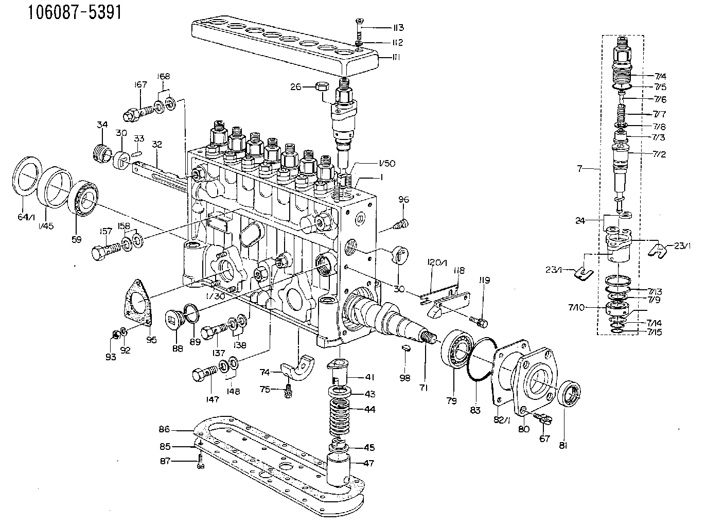
| 1. | [1] | 134050-1120 | PUMP HOUSING |
| 1/30. | [3] | 029040-6020 | STUD |
| 1/45. | [1] | 134311-0000 | SPACER RING |
| 1/50. | [16] | 134138-0000 | STUD |
| 7. | [8] | 134143-2520 | PLUNGER-AND-BARREL ASSY |
| 7/1. | [8] | 134131-1020 | FLANGE BUSHING |
| 7/2. | [8] | 134151-0420 | PLUNGER-AND-BARREL ASSY |
| 7/3. | [8] | 134110-5420 | DELIVERY-VALVE ASSEMBLY |
| 7/4. | [8] | 134116-3200 | FITTING |
| 7/5. | [8] | 029632-2070 | O-RING |
| 7/6. | [8] | 134117-1400 | FILLER PIECE |
| 7/7. | [8] | 134112-0600 | COILED SPRING |
| 7/8. | [8] | 134115-0100 | GASKET |
| 7/9. | [8] | 029302-0140 | PLAIN WASHER |
| 7/10. | [8] | 134135-0200 | CAPSULE |
| 7/11. | [8] | 029602-0010 | LOCKING WASHER |
| 7/12. | [8] | 134137-0000 | SPACER RING |
| 7/13. | [8] | 029632-9030 | O-RING |
| 7/14. | [8] | 029631-5020 | O-RING |
| 7/15. | [8] | 029631-5020 | O-RING |
| 23/1. | [0] | 134139-0000 | SHIM T0.5 |
| 23/1. | [0] | 134139-0000 | SHIM T0.5 |
| 23/1. | [0] | 134139-0100 | SHIM T0.6 |
| 23/1. | [0] | 134139-0200 | SHIM T0.7 |
| 23/1. | [0] | 134139-0300 | SHIM T0.8 |
| 23/1. | [0] | 134139-0400 | SHIM T0.9 |
| 23/1. | [0] | 134139-0500 | SHIM T0.4 |
| 23/1. | [0] | 134139-0600 | SHIM T0.15 |
| 23/1. | [0] | 134139-2300 | SHIM T1.5 |
| 24. | [16] | 134132-0300 | PLAIN WASHER D20&11T2.5 |
| 26. | [16] | 013021-0040 | UNION NUT M10P1.5H8 |
| 30. | [2] | 134001-0000 | BUSHING |
| 30. | [2] | 134001-0000 | BUSHING |
| 32. | [1] | 134258-0000 | CONTROL RACK |
| 33. | [1] | 024030-2030 | BEARING PIN |
| 34. | [1] | 134222-0000 | BUSHING |
| 41. | [8] | 134241-0021 | CONTROL SLEEVE |
| 43. | [8] | 134216-0000 | SLOTTED WASHER |
| 44. | [8] | 134215-0300 | COMPRESSION SPRING |
| 45. | [8] | 134217-0500 | SLOTTED WASHER |
| 47. | [8] | 134200-0020 | TAPPET |
| 47/2. | [1] | 134204-0000 | ROLLER |
| 47/3. | [1] | 134205-0000 | BUSHING |
| 47/4. | [1] | 134203-0000 | BEARING PIN |
| 47/5. | [1] | 131206-0500 | SLIDER |
| 59. | [1] | 016650-2230 | BEARING PLATE |
| 64/1. | [0] | 134303-0000 | SHIM D59.8&43T1.2 |
| 64/1. | [0] | 134303-0100 | SHIM D59.8&43T1.5 |
| 64/1. | [0] | 134303-0200 | SHIM D59.8&43T1.8 |
| 64/1. | [0] | 134303-0300 | SHIM D59.8&43T2.0 |
| 64/1. | [0] | 134303-0400 | SHIM D59.8&43T0.6 |
| 67. | [4] | 029010-6810 | BLEEDER SCREW |
| 71. | [1] | 134381-0700 | CAMSHAFT |
| 74. | [1] | 134306-0000 | BEARING SHELL |
| 75. | [2] | 020106-2040 | BLEEDER SCREW M6P1L20 |
| 79. | [1] | 016650-2230 | BEARING PLATE |
| 80. | [1] | 134316-0100 | COVER |
| 81. | [1] | 026712-5010 | PACKING RING |
| 82/1. | [0] | 134314-0000 | SHIM T0.1 |
| 82/1. | [0] | 134314-0100 | SHIM T0.12 |
| 82/1. | [0] | 134314-0200 | SHIM T0.14 |
| 82/1. | [0] | 134314-0300 | SHIM T0.16 |
| 82/1. | [0] | 134314-0400 | SHIM T0.18 |
| 82/1. | [0] | 134314-0500 | SHIM T0.3 |
| 82/1. | [0] | 134314-0600 | SHIM T0.5 |
| 83. | [1] | 029635-5010 | O-RING |
| 85. | [1] | 134043-0700 | COVER |
| 86. | [1] | 134042-1500 | GASKET |
| 87. | [14] | 012206-1640 | FLAT-HEAD SCREW M6P1L16 |
| 88. | [1] | 134045-0100 | CAPSULE |
| 89. | [1] | 026524-2940 | GASKET D28.9&24.3T2 |
| 92. | [3] | 014110-6440 | LOCKING WASHER |
| 93. | [3] | 013020-6040 | UNION NUT M6P1H5 |
| 95. | [1] | 131041-0800 | GASKET |
| 96. | [8] | 134047-0000 | CAPSULE |
| 98. | [1] | 025805-1910 | WOODRUFF KEY |
| 111. | [1] | 134416-0000 | COVER |
| 112. | [2] | 014530-6540 | TAB WASHER |
| 113. | [2] | 021306-3010 | FLAT-HEAD SCREW |
| 118. | [1] | 134496-1200 | POINTER |
| 119. | [2] | 029020-6210 | BLEEDER SCREW |
| 120/1. | [0] | 139400-0100 | SHIM T0.2 |
| 120/1. | [0] | 139400-0200 | SHIM T0.3 |
| 120/1. | [0] | 139400-0300 | SHIM T0.5 |
| 120/1. | [0] | 139400-0400 | SHIM T1.0 |
| 120/1. | [0] | 139400-7200 | SHIM T0.1 |
| 137. | [1] | 029731-4680 | EYE BOLT |
| 138. | [2] | 026514-1840 | GASKET D17.9&14.2T1 |
| 147. | [1] | 029731-0120 | EYE BOLT |
| 148. | [2] | 026510-1440 | GASKET D13.9&10.2T1 |
| 157. | [1] | 029731-4680 | EYE BOLT |
| 158. | [2] | 026514-1840 | GASKET D17.9&14.2T1 |
| 167. | [1] | 132424-0620 | OVER FLOW VALVE |
| 168. | [2] | 026514-1840 | GASKET D17.9&14.2T1 |
Include in #1:
106871-0142
as FUEL INJECTION PUMP
Cross reference number
Zexel num
Bosch num
Firm num
Name
Information:
Use the following procedure to update the fuel lines group with the new hose assemblies.Note: Follow all the safety precautions before carrying out any work on the machine.Installation of 488-9360 Hose As between Fuel Tank and Primary filter group
Illustration 1 g06107286
View of inner side of left-hand frame
(A) Fuel tank
(1) 488-9360 Hose As
(2) 383-6118 Clip
Remove former 236-5242 Hose As from fuel tank (A) along the left-hand inner frame and replace with 488-9360 Hose As (1). Use two 383-6118 Clips (2) to mount 488-9360 Hose As (1) to the inner frame.
Illustration 2 g06107793
View of hose routing above the steering box assembly
(1) 488-9360 Hose As
(3) 6D-4244 Clip
Continue routing 488-9360 Hose As (1) above the steering box assembly from left to right using two 6D-4244 Clips (3) in place of the former 1S-0994 Clips.
Illustration 3 g06107808
View of hose routing to the primary filter group
(1) 488-9360 Hose As
(3) 6D-4244 Clips
Route 488-9360 Hose As (1) along the frame and up toward the primary filter group using 6D-4244 Clips (3) to secure to the frame.
Illustration 4 g06108256
View of primary filter group location inner side of right-hand frame
(B) Former fitting
(C) Primary filter group
(1) 488-9360 Hose As
(4) 148-8354 Elbow As
If not previously completed, remove former hose (B) along with the related fitting from the connection on primary filter group (C).
Connect 148-8354 Elbow As (4) onto primary filter group (C) where fitting (B) was removed.
Attach 488-9360 Hose As (1) to 148-8354 Elbow As (4).Installation of 488-9362 Hose As Between Fuel Tank and Fuel Return Manifold
Illustration 5 g06108268
View of left inner frame
(D) Former hose 240-8598 Hose As
Remove former return hose assembly (D) from between the fuel tank and the fuel manifold in the engine.Note: Unless specified otherwise, retain all mounting hardware for reuse.
Illustration 6 g06108327
View of new hose route.
(A) Fuel tank
(2) 383-6118 Clip
(5) 488-9362 Hose As
Connect 488-9362 Hose As (5) to fuel tank where the old hose was removed.
Route 488-9362 Hose As (5) back along the left-hand inner frame towards the engine and use two 383-6118 Clips (2) installed previously to secure hose assembly (5) in place.
Illustration 7 g06112935
View of the rear of the engine
(5) 488-9362 Hose As
(6) 9M-8406 Clip
(7) 329-1681 Clip
Finish installing 488-9362 Hose As (5) by routing hose (5) up the rear side of the engine and connecting the hose where former hose (D) was removed.
Secure 488-9362 Hose As (5) using one 9M-8406 Clip (6) and one 329-1681 Clip (7).Installation of 488-9361 Hose As Between Primary Filter Group and Engine
Illustration 8 g06108399
Top view of the engine underneath the hood
(3) 6D-4244 Clip
(8) 488-9361 Hose As
Remove the existing hose assembly between the primary filter group and the engine.
Install 488-9361 Hose As (8) where the former hose was removed.
Use one 6D-4244 Clip (3) to secure hose assembly (8) to the top of the engine.