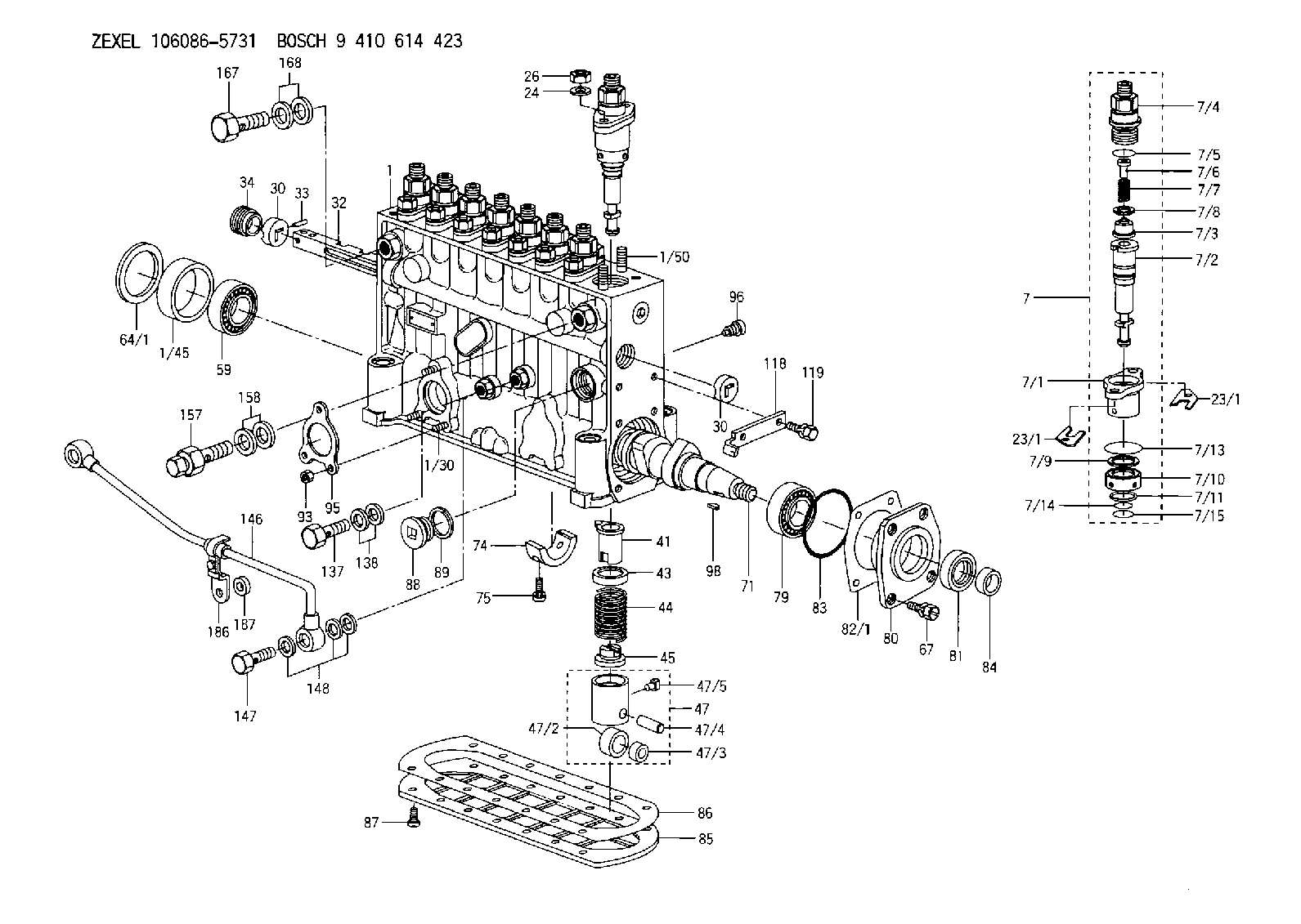
Information fuel-injection pump
BOSCH
9 410 614 423
9410614423
ZEXEL
106086-5731
1060865731
MITSUBISHI
ME756367
me756367
Rating:
Scheme ###:
| 1. | [1] | 134064-8420 | PUMP HOUSING |
| 1/30. | [3] | 029040-6020 | STUD |
| 1/45. | [1] | 134311-0000 | SPACER RING |
| 1/50. | [16] | 134138-0000 | STUD |
| 7. | [8] | 134142-9820 | PLUNGER-AND-BARREL ASSY |
| 7/1. | [8] | 134131-1920 | FLANGE BUSHING |
| 7/2. | [8] | 134101-7920 | PLUNGER-AND-BARREL ASSY P63 |
| 7/3. | [8] | 134110-5020 | DELIVERY-VALVE ASSEMBLY P49 |
| 7/4. | [8] | 134116-2400 | FITTING |
| 7/5. | [8] | 139722-0400 | O-RING |
| 7/6. | [8] | 134117-1400 | FILLER PIECE |
| 7/7. | [8] | 134112-1500 | COILED SPRING |
| 7/8. | [8] | 134115-0100 | GASKET |
| 7/9. | [8] | 029302-0140 | PLAIN WASHER |
| 7/10. | [8] | 134135-0400 | CAPSULE |
| 7/11. | [8] | 029602-0010 | LOCKING WASHER |
| 7/13. | [8] | 139729-0400 | O-RING |
| 7/14. | [8] | 139715-0400 | O-RING |
| 7/15. | [8] | 139715-0400 | O-RING |
| 23/1. | [0] | 139400-0900 | SHIM T0.500 |
| 23/1. | [0] | 139400-0900 | SHIM T0.500 |
| 23/1. | [0] | 139400-1000 | SHIM T0.525 |
| 23/1. | [0] | 139400-1100 | SHIM T0.550 |
| 23/1. | [0] | 139400-1200 | SHIM T0.575 |
| 23/1. | [0] | 139400-1300 | SHIM T0.600 |
| 23/1. | [0] | 139400-1400 | SHIM T0.625 |
| 23/1. | [0] | 139400-1500 | SHIM T0.650 |
| 23/1. | [0] | 139400-1600 | SHIM T0.675 |
| 23/1. | [0] | 139400-1700 | SHIM T0.700 |
| 23/1. | [0] | 139400-1800 | SHIM T0.725 |
| 23/1. | [0] | 139400-1900 | SHIM T0.750 |
| 23/1. | [0] | 139400-2000 | SHIM T0.775 |
| 23/1. | [0] | 139400-2100 | SHIM T0.800 |
| 23/1. | [0] | 139400-2200 | SHIM T0.825 |
| 23/1. | [0] | 139400-2300 | SHIM T0.850 |
| 23/1. | [0] | 139400-2400 | SHIM T0.875 |
| 23/1. | [0] | 139400-2500 | SHIM T0.900 |
| 23/1. | [0] | 139400-2600 | SHIM T0.925 |
| 23/1. | [0] | 139400-2700 | SHIM T0.950 |
| 23/1. | [0] | 139400-2800 | SHIM T0.975 |
| 23/1. | [0] | 139400-2900 | SHIM T1.000 |
| 23/1. | [0] | 139400-3000 | SHIM T1.025 |
| 23/1. | [0] | 139400-3100 | SHIM T1.050 |
| 23/1. | [0] | 139400-3200 | SHIM T1.075 |
| 23/1. | [0] | 139400-3300 | SHIM T1.100 |
| 23/1. | [0] | 139400-3400 | SHIM T1.125 |
| 23/1. | [0] | 139400-3500 | SHIM T1.150 |
| 23/1. | [0] | 139400-3600 | SHIM T1.175 |
| 23/1. | [0] | 139400-3700 | SHIM T1.200 |
| 23/1. | [0] | 139400-3800 | SHIM T1.225 |
| 23/1. | [0] | 139400-3900 | SHIM T1.250 |
| 23/1. | [0] | 139400-4000 | SHIM T1.275 |
| 23/1. | [0] | 139400-4100 | SHIM T1.300 |
| 23/1. | [0] | 139400-4200 | SHIM T1.325 |
| 23/1. | [0] | 139400-4300 | SHIM T1.350 |
| 23/1. | [0] | 139400-4400 | SHIM T1.375 |
| 23/1. | [0] | 139400-4500 | SHIM T1.400 |
| 23/1. | [0] | 139400-4600 | SHIM T1.425 |
| 23/1. | [0] | 139400-4700 | SHIM T1.450 |
| 23/1. | [0] | 139400-4800 | SHIM T1.475 |
| 23/1. | [0] | 139400-4900 | SHIM T1.500 |
| 23/1. | [0] | 139400-5000 | SHIM T1.525 |
| 23/1. | [0] | 139400-5100 | SHIM T1.550 |
| 23/1. | [0] | 139400-5200 | SHIM T1.575 |
| 23/1. | [0] | 139400-5300 | SHIM T1.600 |
| 23/1. | [0] | 139400-5400 | SHIM T1.625 |
| 23/1. | [0] | 139400-5500 | SHIM T1.650 |
| 23/1. | [0] | 139400-5600 | SHIM T1.675 |
| 23/1. | [0] | 139400-5700 | SHIM T1.700 |
| 23/1. | [0] | 139400-5800 | SHIM T1.725 |
| 23/1. | [0] | 139400-5900 | SHIM T1.750 |
| 23/1. | [0] | 139400-6000 | SHIM T1.775 |
| 23/1. | [0] | 139400-6100 | SHIM T1.800 |
| 23/1. | [0] | 139400-6200 | SHIM T1.825 |
| 23/1. | [0] | 139400-6300 | SHIM T1.850 |
| 23/1. | [0] | 139400-6400 | SHIM T1.875 |
| 23/1. | [0] | 139400-6500 | SHIM T1.900 |
| 23/1. | [0] | 139400-6600 | SHIM T1.925 |
| 23/1. | [0] | 139400-6700 | SHIM T1.950 |
| 23/1. | [0] | 139400-6800 | SHIM T1.975 |
| 24. | [16] | 134132-0300 | PLAIN WASHER |
| 26. | [16] | 013021-0040 | UNION NUT M10P1.5H8 |
| 30. | [2] | 134001-0000 | BUSHING |
| 30. | [2] | 134001-0000 | BUSHING |
| 32. | [1] | 134258-2320 | CONTROL RACK |
| 33. | [1] | 024030-2030 | BEARING PIN |
| 34. | [1] | 134222-0000 | BUSHING |
| 41. | [8] | 134241-0021 | CONTROL SLEEVE |
| 43. | [8] | 134216-0000 | SLOTTED WASHER |
| 44. | [8] | 134215-0400 | COMPRESSION SPRING |
| 45. | [8] | 134217-0500 | SLOTTED WASHER |
| 47. | [8] | 134200-0020 | TAPPET |
| 47/2. | [8] | 134204-0000 | ROLLER |
| 47/3. | [8] | 134205-0000 | BUSHING |
| 47/4. | [8] | 134203-0000 | BEARING PIN |
| 47/5. | [8] | 131206-0500 | SLIDER |
| 59. | [1] | 016650-2230 | BEARING PLATE 4T-32205(NSK) |
| 64/1. | [0] | 134303-0000 | SHIM D59.8&43T1.2 |
| 64/1. | [0] | 134303-0100 | SHIM D59.8&43T1.5 |
| 64/1. | [0] | 134303-0200 | SHIM D59.8&43T1.8 |
| 64/1. | [0] | 134303-0300 | SHIM D59.8&43T2.0 |
| 64/1. | [0] | 134303-0400 | SHIM D59.8&43T0.6 |
| 67. | [4] | 029010-6810 | BLEEDER SCREW |
| 71. | [1] | 134381-1800 | CAMSHAFT |
| 74. | [1] | 134306-0100 | BEARING SHELL |
| 75. | [2] | 020106-2040 | BLEEDER SCREW |
| 79. | [1] | 016650-2230 | BEARING PLATE 4T-32205(NSK) |
| 80. | [1] | 134316-1700 | COVER |
| 81. | [1] | 139625-0000 | PACKING RING |
| 82/1. | [0] | 134314-0000 | SHIM T0.1 |
| 82/1. | [0] | 134314-0100 | SHIM T0.12 |
| 82/1. | [0] | 134314-0200 | SHIM T0.14 |
| 82/1. | [0] | 134314-0300 | SHIM T0.16 |
| 82/1. | [0] | 134314-0400 | SHIM T0.18 |
| 82/1. | [0] | 134314-0500 | SHIM T0.3 |
| 82/1. | [0] | 134314-0600 | SHIM T0.5 |
| 83. | [1] | 029635-5010 | O-RING |
| 84. | [1] | 134563-0900 | SLIDING PIECE |
| 85. | [1] | 134043-0700 | COVER |
| 86. | [1] | 134042-1500 | GASKET |
| 87. | [14] | 012206-1640 | FLAT-HEAD SCREW |
| 88. | [1] | 134045-0100 | CAPSULE |
| 89. | [1] | 026524-2940 | GASKET |
| 93. | [3] | 139206-0400 | UNION NUT |
| 95. | [1] | 131041-0800 | GASKET |
| 96. | [8] | 134047-0000 | CAPSULE |
| 98. | [1] | 029470-5010 | WOODRUFF KEY |
| 118. | [1] | 134496-2800 | POINTER |
| 119. | [2] | 020006-1240 | BLEEDER SCREW |
| 137. | [1] | 029731-4680 | EYE BOLT |
| 138. | [2] | 026514-1840 | GASKET |
| 146. | [1] | 134493-1320 | PIPE |
| 147. | [1] | 029731-0490 | EYE BOLT |
| 148. | [3] | 026510-1340 | GASKET |
| 157. | [1] | 131424-8020 | OVER FLOW VALVE |
| 158. | [2] | 029341-4130 | GASKET |
| 167. | [1] | 029731-4680 | EYE BOLT |
| 168. | [2] | 029341-4130 | GASKET |
| 186. | [1] | 134563-8420 | BRACKET |
| 187. | [1] | 134510-8800 | SPACER BUSHING |
Include in #1:
106861-2652
as FUEL INJECTION PUMP
Cross reference number
Zexel num
Bosch num
Firm num
Name
Information:
Unit Injector Mechanism
Illustration 2 g01430766
Typical unit injector mechanism (17) Unit injector (18) Adjusting nut (19) Rocker arm assembly (20) CamshaftThe unit injector mechanism provides the downward force that is required to pressurize the fuel in the unit injector. When a signal is received from the ECM, the unit injector (17) injects the pressurized fuel into the combustion chamber. The camshaft gear is driven by an idler gear which is driven through the front gear train by the crankshaft gear. The gears of the front gear train that are timed must be aligned in order to provide the correct relationship between the piston and valve movement. During assembly of the front gear train, care must be taken in order to correctly align the timing marks of the gears. The camshaft has three camshaft lobes for each cylinder. Two lobes operate the inlet and exhaust valves, and one operates the unit injector mechanism. Force is transferred from the unit injector lobe on camshaft (20) through rocker arm assembly (19) to the top of the unit injector. The adjusting nut (18) allows setting of the unit injector adjustment. Refer to the Testing and Adjusting, "Electronic Unit Injector - Adjust" for the proper setting of the unit injector.Unit Injector
Illustration 3 g01332439
(21) Solenoid (22) Tappet (23) Plunger (24) Barrel (25) Nozzle assemblyOperation of the Electronic Unit Injector
The operation of the Electronic Control Unit (EUI) consists of the following four stages: Pre-injection, Injection, End of injection and Fill. Unit injectors use a plunger and barrel to pump high pressure fuel into the combustion chamber. Components of the injector include the tappet, the plunger, the barrel and nozzle assembly. Components of the nozzle assembly include the spring, the nozzle check, and a nozzle tip. The cartridge valve is made up of the following components: solenoid, armature, poppet valve and poppet spring.The injector is mounted in an injector bore in the cylinder head which has an integral fuel supply passage. The injector sleeve separates the injector from the engine coolant in the water jacket. Some engines use a stainless steel sleeve. The stainless steel sleeve fits into the cylinder head with a light press fit.
Illustration 4 g00942799
Pre-injection (A) Fuel supply pressure (B) Injection pressure (C) Moving parts (D) Mechanical movement (E) Fuel movement.Pre-injection metering starts with the injector plunger and the injector tappet at the top of the fuel injection stroke. When the plunger cavity is full of fuel, the poppet valve is in the open position and the nozzle check is in the open position. Fuel leaves the plunger cavity when the rocker arm pushes down on the tappet and the plunger. Fuel flow that is blocked by the closed nozzle check valve flows past the open poppet valve to the fuel supply passage in the cylinder head. If the solenoid is energized, the poppet valve remains open and the fuel from the plunger cavity continues flowing into the fuel supply passage.
Illustration 5 g00942798
Injection (A) Fuel supply pressure. (B) Injection pressure (C) Moving parts (D) Mechanical movement (E)