Information fuel-injection pump
BOSCH
9 410 613 487
9410613487
ZEXEL
106086-5730
1060865730
MITSUBISHI
ME755697
me755697
Rating:
Scheme ###:
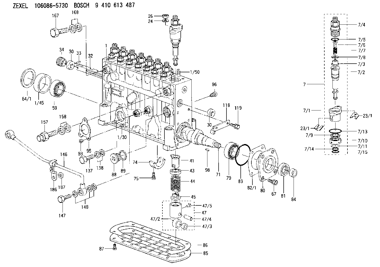
| 1. | [1] | 134064-8420 | PUMP HOUSING |
| 1/30. | [3] | 029040-6020 | STUD |
| 1/45. | [1] | 134311-0000 | SPACER RING |
| 1/50. | [16] | 134138-0000 | STUD |
| 7. | [8] | 134142-9820 | PLUNGER-AND-BARREL ASSY |
| 7/1. | [1] | 134131-1920 | FLANGE BUSHING |
| 7/2. | [1] | 134101-7920 | PLUNGER-AND-BARREL ASSY |
| 7/3. | [1] | 134110-5020 | DELIVERY-VALVE ASSEMBLY |
| 7/4. | [1] | 134116-2400 | FITTING |
| 7/5. | [1] | 139722-0400 | O-RING |
| 7/6. | [1] | 134117-1400 | FILLER PIECE |
| 7/7. | [1] | 134112-1500 | COILED SPRING |
| 7/8. | [1] | 134115-0100 | GASKET |
| 7/9. | [1] | 029302-0140 | PLAIN WASHER |
| 7/10. | [1] | 134135-0200 | CAPSULE |
| 7/11. | [1] | 029602-0010 | LOCKING WASHER |
| 7/13. | [1] | 139729-0400 | O-RING |
| 7/14. | [1] | 139715-0400 | O-RING |
| 7/15. | [1] | 139715-0400 | O-RING |
| 23/1. | [0] | 139400-0900 | SHIM T0.500 |
| 23/1. | [0] | 139400-1000 | SHIM T0.525 |
| 23/1. | [0] | 139400-1100 | SHIM T0.550 |
| 23/1. | [0] | 139400-1100 | SHIM T0.550 |
| 23/1. | [0] | 139400-1200 | SHIM T0.575 |
| 23/1. | [0] | 139400-1300 | SHIM T0.600 |
| 23/1. | [0] | 139400-1400 | SHIM T0.625 |
| 23/1. | [0] | 139400-1500 | SHIM T0.650 |
| 23/1. | [0] | 139400-1600 | SHIM T0.675 |
| 23/1. | [0] | 139400-1700 | SHIM T0.700 |
| 23/1. | [0] | 139400-1800 | SHIM T0.725 |
| 23/1. | [0] | 139400-1900 | SHIM T0.750 |
| 23/1. | [0] | 139400-2000 | SHIM T0.775 |
| 23/1. | [0] | 139400-2100 | SHIM T0.800 |
| 23/1. | [0] | 139400-2200 | SHIM T0.825 |
| 23/1. | [0] | 139400-2300 | SHIM T0.850 |
| 23/1. | [0] | 139400-2400 | SHIM T0.875 |
| 23/1. | [0] | 139400-2500 | SHIM T0.900 |
| 23/1. | [0] | 139400-2600 | SHIM T0.925 |
| 23/1. | [0] | 139400-2700 | SHIM T0.950 |
| 23/1. | [0] | 139400-2800 | SHIM T0.975 |
| 23/1. | [0] | 139400-2900 | SHIM T1.000 |
| 23/1. | [0] | 139400-3000 | SHIM T1.025 |
| 23/1. | [0] | 139400-3100 | SHIM T1.050 |
| 23/1. | [0] | 139400-3200 | SHIM T1.075 |
| 23/1. | [0] | 139400-3300 | SHIM T1.100 |
| 23/1. | [0] | 139400-3400 | SHIM T1.125 |
| 23/1. | [0] | 139400-3500 | SHIM T1.150 |
| 23/1. | [0] | 139400-3600 | SHIM T1.175 |
| 23/1. | [0] | 139400-3700 | SHIM T1.200 |
| 23/1. | [0] | 139400-3800 | SHIM T1.225 |
| 23/1. | [0] | 139400-3900 | SHIM T1.250 |
| 23/1. | [0] | 139400-4000 | SHIM T1.275 |
| 23/1. | [0] | 139400-4100 | SHIM T1.300 |
| 23/1. | [0] | 139400-4200 | SHIM T1.325 |
| 23/1. | [0] | 139400-4300 | SHIM T1.350 |
| 23/1. | [0] | 139400-4400 | SHIM T1.375 |
| 23/1. | [0] | 139400-4500 | SHIM T1.400 |
| 23/1. | [0] | 139400-4600 | SHIM T1.425 |
| 23/1. | [0] | 139400-4700 | SHIM T1.450 |
| 23/1. | [0] | 139400-4800 | SHIM T1.475 |
| 23/1. | [0] | 139400-4900 | SHIM T1.500 |
| 23/1. | [0] | 139400-5000 | SHIM T1.525 |
| 23/1. | [0] | 139400-5100 | SHIM T1.550 |
| 23/1. | [0] | 139400-5200 | SHIM T1.575 |
| 23/1. | [0] | 139400-5300 | SHIM T1.600 |
| 23/1. | [0] | 139400-5400 | SHIM T1.625 |
| 23/1. | [0] | 139400-5500 | SHIM T1.650 |
| 23/1. | [0] | 139400-5600 | SHIM T1.675 |
| 23/1. | [0] | 139400-5700 | SHIM T1.700 |
| 23/1. | [0] | 139400-5800 | SHIM T1.725 |
| 23/1. | [0] | 139400-5900 | SHIM T1.750 |
| 23/1. | [0] | 139400-6000 | SHIM T1.775 |
| 23/1. | [0] | 139400-6100 | SHIM T1.800 |
| 23/1. | [0] | 139400-6200 | SHIM T1.825 |
| 23/1. | [0] | 139400-6300 | SHIM T1.850 |
| 23/1. | [0] | 139400-6400 | SHIM T1.875 |
| 23/1. | [0] | 139400-6500 | SHIM T1.900 |
| 23/1. | [0] | 139400-6600 | SHIM T1.925 |
| 23/1. | [0] | 139400-6700 | SHIM T1.950 |
| 23/1. | [0] | 139400-6800 | SHIM T1.975 |
| 24. | [16] | 134132-0300 | PLAIN WASHER D20&11T2.5 |
| 26. | [16] | 013021-0040 | UNION NUT M10P1.5H8 |
| 30. | [2] | 134001-0000 | BUSHING |
| 30. | [2] | 134001-0000 | BUSHING |
| 32. | [1] | 134258-0420 | CONTROL RACK |
| 33. | [1] | 024030-2030 | BEARING PIN |
| 34. | [1] | 134222-0000 | BUSHING |
| 41. | [8] | 134241-0021 | CONTROL SLEEVE |
| 43. | [8] | 134216-0000 | SLOTTED WASHER |
| 44. | [8] | 134215-0400 | COMPRESSION SPRING |
| 45. | [8] | 134217-0500 | SLOTTED WASHER |
| 47. | [8] | 134200-0020 | TAPPET |
| 47/2. | [1] | 134204-0000 | ROLLER |
| 47/3. | [1] | 134205-0000 | BUSHING |
| 47/4. | [1] | 134203-0000 | BEARING PIN |
| 47/5. | [1] | 131206-0500 | SLIDER |
| 59. | [1] | 016650-2230 | BEARING PLATE |
| 64/1. | [0] | 134303-0000 | SHIM D59.8&43T1.2 |
| 64/1. | [0] | 134303-0100 | SHIM D59.8&43T1.5 |
| 64/1. | [0] | 134303-0200 | SHIM D59.8&43T1.8 |
| 64/1. | [0] | 134303-0300 | SHIM D59.8&43T2.0 |
| 64/1. | [0] | 134303-0400 | SHIM D59.8&43T0.6 |
| 67. | [4] | 029010-6810 | BLEEDER SCREW |
| 71. | [1] | 134381-1800 | CAMSHAFT |
| 74. | [1] | 134306-0100 | BEARING SHELL |
| 75. | [2] | 020106-2040 | BLEEDER SCREW M6P1L20 |
| 79. | [1] | 016650-2230 | BEARING PLATE |
| 80. | [1] | 134316-1700 | COVER |
| 81. | [1] | 139625-0000 | PACKING RING |
| 82/1. | [0] | 134314-0000 | SHIM T0.1 |
| 82/1. | [0] | 134314-0100 | SHIM T0.12 |
| 82/1. | [0] | 134314-0200 | SHIM T0.14 |
| 82/1. | [0] | 134314-0300 | SHIM T0.16 |
| 82/1. | [0] | 134314-0400 | SHIM T0.18 |
| 82/1. | [0] | 134314-0500 | SHIM T0.3 |
| 82/1. | [0] | 134314-0600 | SHIM T0.5 |
| 83. | [1] | 029635-5010 | O-RING |
| 84. | [1] | 134563-0900 | SLIDING PIECE |
| 85. | [1] | 134043-0700 | COVER |
| 86. | [1] | 134042-1500 | GASKET |
| 87. | [14] | 012206-1640 | FLAT-HEAD SCREW M6P1L16 |
| 88. | [1] | 134045-0100 | CAPSULE |
| 89. | [1] | 026524-2940 | GASKET D28.9&24.3T2 |
| 93. | [3] | 139206-0400 | UNION NUT |
| 95. | [1] | 131041-0800 | GASKET |
| 96. | [8] | 134047-0000 | CAPSULE |
| 98. | [1] | 025805-1910 | WOODRUFF KEY |
| 118. | [1] | 134496-2800 | POINTER |
| 119. | [2] | 020006-1240 | BLEEDER SCREW M6P1L12 4T |
| 137. | [1] | 134430-2620 | EYE BOLT |
| 138. | [2] | 026514-1840 | GASKET D17.9&14.2T1 |
| 146. | [1] | 134493-1320 | PIPE |
| 147. | [1] | 029731-0490 | EYE BOLT |
| 148. | [3] | 026510-1340 | GASKET D13.4&10.2T1 |
| 157. | [1] | 131424-8020 | OVER FLOW VALVE |
| 158. | [2] | 029341-4130 | GASKET D20&13.8T2* |
| 167. | [1] | 029731-4680 | EYE BOLT |
| 168. | [2] | 029341-4130 | GASKET D20&13.8T2* |
| 186. | [1] | 134563-8420 | BRACKET |
| 187. | [1] | 134510-8800 | SPACER BUSHING |
Cross reference number
Zexel num
Bosch num
Firm num
Name
Information:
Introduction
Do not perform any procedure in this Special Instruction until you have read this information and you understand this information.Required Parts
Table 1
Required Parts
Qty New Part Number Part Name Former Part Number
1 347-5556 Fuel Lines Kit
1 352-8532 Fuel Lines Kit 343-8867
1 352-8533 Fuel Lines Kit 310-6030 Installing the Bracket on the Line for Cylinder 5
Illustration 1 g02045118
Place the bottom portion of the clip (2) on the line for cylinder 5 before installing the line. Ensure that the grommet (1) does not become bent or misaligned.
Illustration 2 g02045093
Install the line for cylinder 5 and hand tighten the nuts on both ends of the line. Hand tighten the nut on the end that attaches to the rail (10) first and then hand tighten the nut on the other end (11) .
Illustration 3 g02045500
An alternate configuration
Illustration 4 g02045502
An alternate configuration
Install the new post (3) and the stud (8). Hand tighten the locking nut (7) on the stud.
Install the top portion of the clip (2) and ensure that the tab is tightly secured on the bottom portion of the clip. Ensure that the bolt hole on the clip and the bolt hole on the new bracket are aligned before tightening the bolt for the new bracket.
Thread the bolt (4) through the post and the clip and hand tighten the nut (5) .
Insert the threaded backing (9) on the back side of the post and hand tighten the allen head screw (6) .
Tighten the nut (10) on the end of the line for cylinder 5 that attaches to the rail and then tighten the other end (11).
Tighten the nut (7) on the stud for the post.
Tighten the nut (5) that secures the clip to the post.
Tighten the allen head screw on the spacer (9) on the back of the post.Note: Failure to correctly place the grommet (1) in the clamp could result in a failed fuel line.