Information fuel-injection pump
BOSCH
9 410 611 907
9410611907
ZEXEL
106069-8100
1060698100
Rating:
Scheme ###:
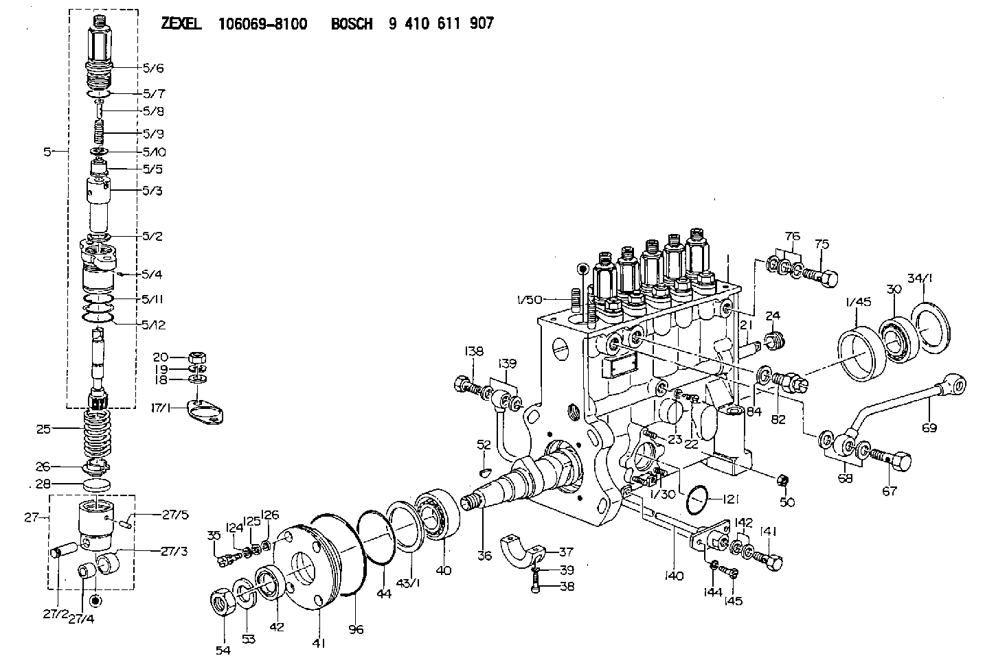
| 1. | [1] | 134000-8420 | PUMP HOUSING |
| 1/30. | [3] | 029040-6020 | STUD |
| 1/45. | [1] | 134311-0000 | SPACER RING |
| 1/50. | [12] | 029041-2100 | STUD |
| 5. | [6] | 134143-8420 | PLUNGER-AND-BARREL ASSY |
| 5/2. | [1] | 029331-9040 | GASKET |
| 5/3. | [1] | 134101-9320 | PLUNGER-AND-BARREL ASSY |
| 5/4. | [1] | 134563-0600 | BEARING PIN |
| 5/5. | [1] | 134110-6220 | DELIVERY-VALVE ASSEMBLY |
| 5/6. | [1] | 134116-3020 | FITTING |
| 5/7. | [1] | 029632-5080 | O-RING |
| 5/8. | [1] | 134117-0500 | FILLER PIECE |
| 5/9. | [1] | 134112-2000 | COILED SPRING |
| 5/10. | [1] | 134115-0100 | GASKET |
| 5/11. | [1] | 029632-9040 | O-RING |
| 5/12. | [1] | 029632-9040 | O-RING |
| 17/1. | [0] | 134139-2400 | SHIM T0.15 |
| 17/1. | [0] | 134139-2500 | SHIM T0.4 |
| 17/1. | [0] | 134139-2600 | SHIM T0.5 |
| 17/1. | [0] | 134139-2700 | SHIM T0.6 |
| 17/1. | [0] | 134139-2800 | SHIM T0.7 |
| 17/1. | [0] | 134139-2900 | SHIM T0.8 |
| 17/1. | [0] | 134139-3000 | SHIM T0.9 |
| 17/1. | [0] | 134139-3100 | SHIM T1.0 |
| 18. | [12] | 029301-2330 | PLAIN WASHER |
| 19. | [12] | 014111-2440 | LOCKING WASHER D21.5&12.2T3 |
| 20. | [12] | 013021-2140 | UNION NUT M12P1.75H10 |
| 21. | [1] | 134256-2000 | CONTROL RACK |
| 22. | [1] | 134226-0000 | FLAT-HEAD SCREW |
| 23. | [1] | 134510-3900 | GASKET |
| 24. | [1] | 134222-0100 | BUSHING |
| 25. | [6] | 134215-0100 | COMPRESSION SPRING |
| 26. | [6] | 134217-0200 | SLOTTED WASHER |
| 27. | [6] | 134200-0520 | TAPPET |
| 27/2. | [1] | 134203-0100 | BEARING PIN |
| 27/3. | [1] | 134204-0100 | ROLLER |
| 27/4. | [1] | 134205-0000 | BUSHING |
| 27/5. | [1] | 134213-0000 | BEARING PIN |
| 28. | [6] | 134140-0400 | SPRING SEAT D14T3.9 |
| 30. | [1] | 016650-2230 | BEARING PLATE |
| 34/1. | [0] | 134303-0000 | SHIM D59.8&43T1.2 |
| 34/1. | [0] | 134303-0100 | SHIM D59.8&43T1.5 |
| 34/1. | [0] | 134303-0200 | SHIM D59.8&43T1.8 |
| 34/1. | [0] | 134303-0300 | SHIM D59.8&43T2.0 |
| 34/1. | [0] | 134303-0400 | SHIM D59.8&43T0.6 |
| 35. | [4] | 029050-6360 | FLAT-HEAD SCREW |
| 36. | [1] | 134371-3700 | CAMSHAFT |
| 37. | [1] | 134305-0000 | BEARING SHELL |
| 38. | [2] | 029020-6140 | HEX-SOCKET-HEAD CAP SCREW |
| 39. | [2] | 134510-3900 | GASKET |
| 40. | [1] | 016650-2230 | BEARING PLATE |
| 41. | [1] | 134316-2400 | COVER |
| 42. | [1] | 026712-5020 | PACKING RING |
| 43/1. | [0] | 134314-0000 | SHIM T0.1 |
| 43/1. | [0] | 134314-0100 | SHIM T0.12 |
| 43/1. | [0] | 134314-0200 | SHIM T0.14 |
| 43/1. | [0] | 134314-0300 | SHIM T0.16 |
| 43/1. | [0] | 134314-0400 | SHIM T0.18 |
| 43/1. | [0] | 134314-0500 | SHIM T0.3 |
| 43/1. | [0] | 134314-0600 | SHIM T0.5 |
| 44. | [1] | 029635-5050 | O-RING |
| 50. | [3] | 139206-0400 | UNION NUT |
| 52. | [1] | 025805-1910 | WOODRUFF KEY |
| 53. | [1] | 014111-8410 | LOCKING WASHER |
| 54. | [1] | 139218-0000 | UNION NUT |
| 67. | [1] | 029731-4680 | EYE BOLT |
| 68. | [2] | 029341-4130 | GASKET D20&13.8T2* |
| 69. | [1] | 134433-4720 | PIPE |
| 75. | [1] | 029731-4280 | EYE BOLT |
| 76. | [3] | 029341-4130 | GASKET D20&13.8T2* |
| 82. | [1] | 134420-0020 | BLEEDER SCREW |
| 84. | [1] | 026514-1840 | GASKET D17.9&14.2T1 |
| 96. | [1] | 029639-0030 | O-RING |
| 121. | [1] | 029633-1020 | O-RING |
| 124. | [4] | 029320-6010 | LOCKING WASHER |
| 125. | [4] | 029300-6170 | SHIM D12&6.2T1 |
| 126. | [4] | 029340-6120 | GASKET |
| 138. | [1] | 029731-4680 | EYE BOLT |
| 139. | [2] | 029341-4130 | GASKET D20&13.8T2* |
| 140. | [1] | 134433-1720 | PIPE |
| 141. | [1] | 029731-4680 | EYE BOLT |
| 142. | [2] | 029341-4130 | GASKET D20&13.8T2* |
| 144. | [2] | 014110-8440 | LOCKING WASHER |
| 145. | [2] | 010038-2040 | BLEEDER SCREW M8P1.25L20 |
Cross reference number
Zexel num
Bosch num
Firm num
Name
Information:
Accidental engine starting can cause injury or death to personnel working on the equipment.To avoid accidental engine starting, disconnect the battery cable from the negative (−) battery terminal. Completely tape all metal surfaces of the disconnected battery cable end in order to prevent contact with other metal surfaces which could activate the engine electrical system.Place a Do Not Operate tag at the Start/Stop switch location to inform personnel that the equipment is being worked on.
2301A Electric Governor Control
The 2301A Electric Governor Control activates all of the components that are in the electric protection system. The components are activated in the same manner when the nonelectric governor is used. One difference exists in the main circuit. The fuel shutoff solenoid (FSOS) (line 43) is not used.When the electric governor control is used, the engine must run in a normal condition in order for the electric circuit to operate in the manner that is described below.
Current flows from the terminals (TS-28) (line 43) and (TS-31) (line 44), which are located on the terminal strip in the junction box.
Current from terminals (TS-28) (line 43) and (TS-31) (line 44) flows through the preregulator (PR) (line 48) or the fuse (F4) to the electric governor control.
When the engine flywheel is rotating, the current also flows through the electric governor actuator (EGA) (line 52). When a fault in the system causes the current to energize the slave relay (SR1), the following events occur in the electric circuit in order to stop the engine.
The slave relay (SR1) opens across the contacts (SR1-30) and (SR1-87a) (line 45). The relay closes across the contacts (SR1-30) and (SR1-87) (line 43).
When the circuit opens across contacts (SR1-30) and (SR1-87a), the current is stopped to the electric governor control.
Current to the electric governor actuator (EGA) is also stopped.
The mechanical spring load in the electric governor actuator (EGA) will now move the fuel control rod in order to stop fuel flow to the engine. Note: With the exception of the differences that are described in this section of the manual, all of the fault circuits in the electric protection system are identical for the 2301A Electric Governor Control and for the nonelectric governor control.
Illustration 3 g00292636
Junction Box Wiring for ETR protection