Information fuel-injection pump
BOSCH
9 410 613 260
9410613260
ZEXEL
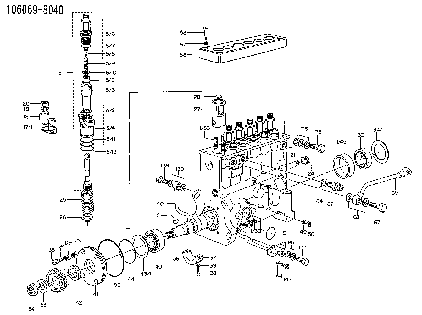
106069-8040
1060698040
Rating:
Scheme ###:
| 1. | [1] | 134000-8420 | PUMP HOUSING |
| 1/30. | [3] | 029040-6020 | STUD |
| 1/45. | [1] | 134311-0000 | SPACER RING |
| 1/50. | [12] | 029041-2100 | STUD |
| 5. | [6] | 134143-7920 | PLUNGER-AND-BARREL ASSY |
| 5/2. | [1] | 029331-9040 | GASKET |
| 5/3. | [1] | 134151-2720 | PLUNGER-AND-BARREL ASSY |
| 5/4. | [1] | 134563-0600 | BEARING PIN |
| 5/5. | [1] | 134110-6220 | DELIVERY-VALVE ASSEMBLY |
| 5/6. | [1] | 134116-3020 | FITTING |
| 5/7. | [1] | 029632-5070 | O-RING |
| 5/8. | [1] | 134117-0500 | FILLER PIECE |
| 5/9. | [1] | 134112-2000 | COILED SPRING |
| 5/10. | [1] | 134115-0100 | GASKET |
| 5/11. | [1] | 029632-9030 | O-RING |
| 5/12. | [1] | 029632-9030 | O-RING |
| 17/1. | [0] | 134139-2400 | SHIM T0.15 |
| 17/1. | [0] | 134139-2500 | SHIM T0.4 |
| 17/1. | [0] | 134139-2600 | SHIM T0.5 |
| 17/1. | [0] | 134139-2700 | SHIM T0.6 |
| 17/1. | [0] | 134139-2800 | SHIM T0.7 |
| 17/1. | [0] | 134139-2900 | SHIM T0.8 |
| 17/1. | [0] | 134139-3000 | SHIM T0.9 |
| 17/1. | [0] | 134139-3100 | SHIM T1.0 |
| 18. | [12] | 029301-2330 | PLAIN WASHER |
| 19. | [12] | 014111-2440 | LOCKING WASHER D21.5&12.2T3 |
| 20. | [12] | 013021-2140 | UNION NUT M12P1.75H10 |
| 21. | [1] | 134256-2000 | CONTROL RACK |
| 22. | [1] | 134226-0000 | FLAT-HEAD SCREW |
| 23. | [1] | 134510-3900 | GASKET |
| 24. | [1] | 134222-0100 | BUSHING |
| 25. | [6] | 134215-0100 | COMPRESSION SPRING |
| 26. | [6] | 134217-0200 | SLOTTED WASHER |
| 27. | [6] | 134200-0520 | TAPPET |
| 27/2. | [1] | 134203-0100 | BEARING PIN |
| 27/3. | [1] | 134204-0100 | ROLLER |
| 27/4. | [1] | 134205-0000 | BUSHING |
| 27/5. | [1] | 134213-0000 | BEARING PIN |
| 28. | [6] | 134140-0400 | SPRING SEAT D14T3.9 |
| 30. | [1] | 016650-2230 | BEARING PLATE |
| 34/1. | [0] | 134303-0000 | SHIM D59.8&43T1.2 |
| 34/1. | [0] | 134303-0100 | SHIM D59.8&43T1.5 |
| 34/1. | [0] | 134303-0200 | SHIM D59.8&43T1.8 |
| 34/1. | [0] | 134303-0300 | SHIM D59.8&43T2.0 |
| 34/1. | [0] | 134303-0400 | SHIM D59.8&43T0.6 |
| 35. | [4] | 029050-6360 | FLAT-HEAD SCREW |
| 36. | [1] | 134371-3700 | CAMSHAFT |
| 37. | [1] | 134305-0000 | BEARING SHELL |
| 38. | [2] | 029020-6140 | HEX-SOCKET-HEAD CAP SCREW |
| 39. | [2] | 134510-3900 | GASKET |
| 40. | [1] | 016650-2230 | BEARING PLATE |
| 41. | [1] | 134316-2400 | COVER |
| 42. | [1] | 026712-5010 | PACKING RING |
| 43/1. | [0] | 134314-0000 | SHIM T0.1 |
| 43/1. | [0] | 134314-0100 | SHIM T0.12 |
| 43/1. | [0] | 134314-0200 | SHIM T0.14 |
| 43/1. | [0] | 134314-0300 | SHIM T0.16 |
| 43/1. | [0] | 134314-0400 | SHIM T0.18 |
| 43/1. | [0] | 134314-0500 | SHIM T0.3 |
| 43/1. | [0] | 134314-0600 | SHIM T0.5 |
| 44. | [1] | 029635-5010 | O-RING |
| 50. | [3] | 139206-0400 | UNION NUT |
| 52. | [1] | 025805-1910 | WOODRUFF KEY |
| 53. | [1] | 014111-8410 | LOCKING WASHER |
| 54. | [1] | 139218-0000 | UNION NUT |
| 56. | [1] | 134416-1500 | COVER |
| 57. | [2] | 014530-6540 | TAB WASHER |
| 58. | [2] | 021306-3940 | FLAT-HEAD SCREW |
| 67. | [1] | 029731-4680 | EYE BOLT |
| 68. | [2] | 029341-4130 | GASKET D20&13.8T2* |
| 69. | [1] | 134433-4720 | PIPE |
| 75. | [1] | 029731-4280 | EYE BOLT |
| 76. | [3] | 029341-4130 | GASKET D20&13.8T2* |
| 82. | [1] | 134420-0020 | BLEEDER SCREW |
| 84. | [1] | 026514-1840 | GASKET D17.9&14.2T1 |
| 96. | [1] | 029639-0020 | O-RING |
| 121. | [1] | 029633-1010 | O-RING |
| 124. | [4] | 029320-6010 | LOCKING WASHER |
| 125. | [4] | 029300-6170 | SHIM D12&6.2T1 |
| 126. | [4] | 029340-6120 | GASKET |
| 138. | [1] | 029731-4680 | EYE BOLT |
| 139. | [2] | 029341-4130 | GASKET D20&13.8T2* |
| 140. | [1] | 134433-1720 | PIPE |
| 141. | [1] | 029731-4680 | EYE BOLT |
| 142. | [2] | 029341-4130 | GASKET D20&13.8T2* |
| 144. | [2] | 014110-8440 | LOCKING WASHER |
| 145. | [2] | 010038-2040 | BLEEDER SCREW M8P1.25L20 |
Cross reference number
Zexel num
Bosch num
Firm num
Name
Information:
Shutdowns
A shutdown secures the fuel and a shutdown secures the air to the engine. A fuel shutoff solenoid may be located in the fuel actuator. The fuel shutoff solenoid is energized. The injector is driven to the off position. This secures the fuel.The air shutoff solenoid secures the air. When this solenoid is activated compressed air flows to the air damper. The air releases a pin. When the pin is released, a spring closes the air damper. This secures the combustion air supply from the turbochargers to the aftercooler.Note: The air damper must be MANUALLY reset before the engine can be restarted. The Marine Engine Control Panel must also be reset with the "RESET" switch before the MMS will allow starting. The panel may not be reset until the engine has stopped rotating. Determine the cause of the shutdown and correct the problem prior to engine operation.
Table 2
Shutdowns of the Marine Monitoring System
Description Sensor Location
Group Part Number (1) Set Point Source of the Alarm
Pressure
Low Oil Pressure 142-5916 or 146-9438 Block 1
105 kPa (15 psi) @LS
260 kPa (38) @HS Low Speed Oil Contactor or High Speed Oil Contactor, or the Lube Oil Filter Outlet Pressure Transducer
High Crankcase Pressure 147-2369 In-line 142-5919 Vee
1 kPa (.15 psi) Crankcase pressure contactor
Temperature
High Jacket Water Outlet Temperature 142-5916 or 146-9438 Block 4
109 °C (228 °F) Jacket Water Contactor or Optional Transducer
Miscellaneous
Oil Mist Detector Various Contact Closure Oil Mist Detector - Not in all engines
Overspeed 146-5522, 146-5523, 146-5524, 146-5525 113% of Rated Speed Engine Speed Switch and MMS
Metal Particle Detection Basic Engine Metal Particles in Oil Plus 5 Seconds Metal Particle Detector
( 1 ) The group part numbers are provided for reference only. For individual part numbers see Reference Information, "Reference Parts Information".Low Speed - The engine speed is below 75% of the rated engine speed.High Speed - The engine speed is above 75% of the rated engine speed.The "Sensor Failure Alarm" Screen
The "Sensor Failure Alarm" screen is displayed when unexpected signals are received by the PLC. The alarm monitors sensors which can produce alarms or shutdowns.
Table 3
Sensor Failure Alarms for the Marine Monitoring System
Description Sensor Location
Group Part Number (1) Set Point Source of the Alarm
RTD/PT 100 Failures Various
< -50 °C (-58 °F) or
> 150 °C (302 °F) Lube oil, After Cooler/Oil Cooler, Jacket Water, and Inlet Manifold Temperatures
Thermocouples Various
< -50 °C (-58 °F) or
> 700 °C (1292 °F) Individual Cylinder, Pre-Turbine, and Stack Thermocouples
4-20mA Transducers Various < 3.5 mA or > 20.15 mA Engine Speed Transducer, Lube Oil and Fuel pressure transducers
Contactors Various No signal